
Page 309 - Cam Design Handbook
P. 309
THB10 9/19/03 7:28 PM Page 297
CAM MANUFACTURING 297
0.0001 in.
b b a
a
c Cam
Cam
c
(a) Circular cam with (b) Cam with circular
0.0001 in. flat arc and straight lines
(y discontinuity). (y discontinuity).
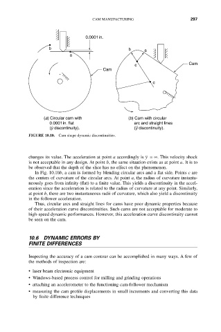
FIGURE 10.10. Cam shape dynamic discontinuities.
¨
changes its value. The acceleration at point a accordingly is y =•. This velocity shock
is not acceptable in any design. At point b, the same situation exists as at point a. It is to
be observed that the depth of the slice has no effect on the phenomenon.
In Fig. 10.10b, a cam is formed by blending circular arcs and a flat side. Points c are
the centers of curvature of the circular arcs. At point a, the radius of curvature instanta-
neously goes from infinity (flat) to a finite value. This yields a discontinuity in the accel-
eration since the acceleration is related to the radius of curvature at any point. Similarly,
at point b, there are two instantaneous radii of curvature, which also yield a discontinuity
in the follower acceleration.
Thus, circular arcs and straight lines for cams have poor dynamic properties because
of their acceleration curve discontinuities. Such cams are not acceptable for moderate to
high-speed dynamic performances. However, this acceleration curve discontinuity cannot
be seen on the cam.
10.6 DYNAMIC ERRORS BY
FINITE DIFFERENCES
Inspecting the accuracy of a cam contour can be accomplished in many ways. A few of
the methods of inspection are:
• laser beam electronic equipment
• Windows-based process control for milling and grinding operations
• attaching an accelerometer to the functioning cam-follower mechanism
• measuring the cam profile displacements in small increments and converting this data
by finite difference techniques