
Page 307 - Cam Design Handbook
P. 307
THB10 9/19/03 7:28 PM Page 295
CAM MANUFACTURING 295
± Tolerance in x direction
Actual cam Desired profile
profile
Normal
distribution
curve ± Tolerance lines
in Y direction
Dq
Actual machine
setting point
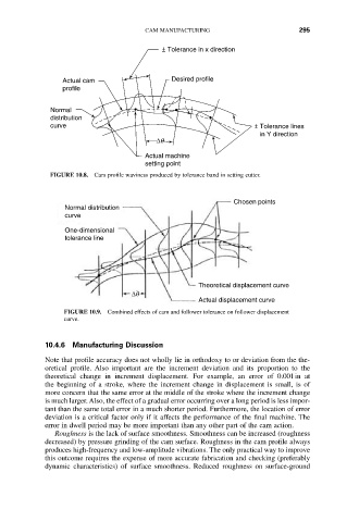
FIGURE 10.8. Cam profile waviness produced by tolerance band in setting cutter.
Chosen points
Normal distribution
curve
One-dimensional
tolerance line
Theoretical displacement curve
Dq
Actual displacement curve
FIGURE 10.9. Combined effects of cam and follower tolerance on follower displacement
curve.
10.4.6 Manufacturing Discussion
Note that profile accuracy does not wholly lie in orthodoxy to or deviation from the the-
oretical profile. Also important are the increment deviation and its proportion to the
theoretical change in increment displacement. For example, an error of 0.001in at
the beginning of a stroke, where the increment change in displacement is small, is of
more concern that the same error at the middle of the stroke where the increment change
is much larger. Also, the effect of a gradual error occurring over a long period is less impor-
tant than the same total error in a much shorter period. Furthermore, the location of error
deviation is a critical factor only if it affects the performance of the final machine. The
error in dwell period may be more important than any other part of the cam action.
Roughness is the lack of surface smoothness. Smoothness can be increased (roughness
decreased) by pressure grinding of the cam surface. Roughness in the cam profile always
produces high-frequency and low-amplitude vibrations. The only practical way to improve
this outcome requires the expense of more accurate fabrication and checking (preferably
dynamic characteristics) of surface smoothness. Reduced roughness on surface-ground