
Page 535 - Cam Design Handbook
P. 535
THB15 9/19/03 8:03 PM Page 523
CAMS IN MICROELECTROMECHANICAL SYSTEMS 523
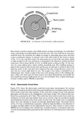
FIGURE 15.13. (d). Schematic of the electrostatic wobble micromotor.
drive motors, top-drive motors, and wobble motors are three such designs. In a side-drive
motor, stator poles circumferentially surround the rotor. The rotor itself has its own gear-
teeth-like poles. By switching the voltage on groups of alternating stator poles, the rotor
is put in continuous rotation. A cutaway view of the solid model of this motor is shown
in Fig. 15.13c. In a top-drive motor, the stator poles are on top of the rotor poles, which
is made possible by the way polysilicon is deposited on the selectively etched sacrificial
oxide layer. This is shown in Fig. 15.13b. A wobble motor, as shown in Fig. 15.13d, con-
sists of a rotor without poles, which wobbles around the post. The wobbling distance is
equal to the clearance between the rotor and the post. Its principle is similar to that of the
harmonic motor in the sense that each rotation of the rotor around the post causes it to
turn only by a small angle about its axis. The torque in this motor is multiplied by its
inherent gear ratio, which is equal to the ratio of the bearing radius to the wobbling dis-
tance. These and other types of rotary motors have been demonstrated successfully but
their significant practical applications are yet to be developed. Next, a linear microactua-
tor that is widely used in MEMS is described.
15.7.2 Electrostatic Comb Drive
Figure 15.14 shows the electrostatic comb-drive-type linear microactuator. Its working
principle is based on the electrostatic force generated between misaligned capacitor plates,
which tends to pull them back together. In the comb-drive design several such capacitor
plate pairs exist because of the interdigitated comb-finger design. This enhances the com-
bined force generated by all of them. The combs that move relative to the fixed combs are
attached to a central mass that shuttles from side to side by virtue of a symmetric design
and alternating activation of the fixed combs on either side. The shuttle mass is suspended
freely above the substrate by means of elastically deformable beams. The design shown
in Fig. 15.14 has a folded-beam suspension, which has high flexibility in the direction of
actuation and high stiffness in the perpendicular direction. This actuator is used in many
MEMS devices including some commercially available products. A mechanism that con-
verts the translational motion generated by the comb drive to rotational motion is described
next.