
Page 530 - Cam Design Handbook
P. 530
THB15 9/19/03 8:03 PM Page 518
518 CAM DESIGN HANDBOOK
another component. If a wrong decision is made during the sequence, the pin gets stuck
in the wheel. This device is equipped with an antireverse spring so that an incorrect
sequence cannot be corrected by trial and error. Amodified design with a translating groove
cam is discussed next.
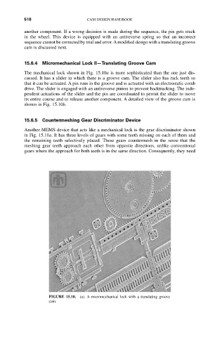
15.6.4 Micromechanical Lock II—Translating Groove Cam
The mechanical lock shown in Fig. 15.10a is more sophisticated than the one just dis-
cussed. It has a slider in which there is a groove cam. The slider also has rack teeth so
that it can be actuated. A pin runs in the groove and is actuated with an electrostatic comb
drive. The slider is engaged with an antireverse pinion to prevent backtracking. The inde-
pendent actuations of the slider and the pin are coordinated to permit the slider to move
its entire course and to release another component. A detailed view of the groove cam is
shown in Fig. 15.10b.
15.6.5 Countermeshing Gear Discriminator Device
Another MEMS device that acts like a mechanical lock is the gear discriminator shown
in Fig. 15.11a. It has three levels of gears with some teeth missing on each of them and
the remaining teeth selectively placed. These gears countermesh in the sense that the
meshing gear teeth approach each other from opposite directions, unlike conventional
gears where the approach for both teeth is in the same direction. Consequently, they need
FIGURE 15.10. (a). A micromechanical lock with a translating groove
cam.