
Page 527 - Cam Design Handbook
P. 527
THB15 9/19/03 8:03 PM Page 515
CAMS IN MICROELECTROMECHANICAL SYSTEMS 515
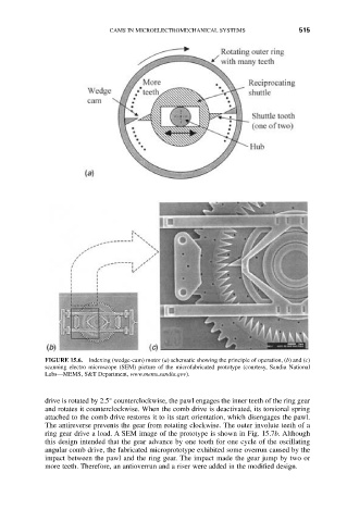
FIGURE 15.6. Indexing (wedge-cam) motor (a) schematic showing the principle of operation, (b) and (c)
scanning electro microscope (SEM) picture of the microfabricated prototype (courtesy, Sandia National
Labs—MEMS, S&T Department, www.mems.sandia.gov).
drive is rotated by 2.5° counterclockwise, the pawl engages the inner teeth of the ring gear
and rotates it counterclockwise. When the comb drive is deactivated, its torsional spring
attached to the comb drive restores it to its start orientation, which disengages the pawl.
The antireverse prevents the gear from rotating clockwise. The outer involute teeth of a
ring gear drive a load. A SEM image of the prototype is shown in Fig. 15.7b. Although
this design intended that the gear advance by one tooth for one cycle of the oscillating
angular comb drive, the fabricated microprototype exhibited some overrun caused by the
impact between the pawl and the ring gear. The impact made the gear jump by two or
more teeth. Therefore, an antioverrun and a riser were added in the modified design.