
Page 532 - Cam Design Handbook
P. 532
THB15 9/19/03 8:03 PM Page 520
520 CAM DESIGN HANDBOOK
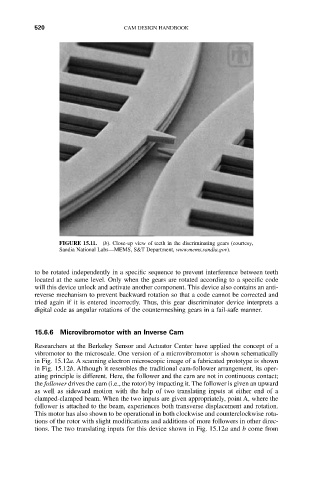
FIGURE 15.11. (b). Close-up view of teeth in the discriminating gears (courtesy,
Sandia National Labs—MEMS, S&T Department, www.mems.sandia.gov).
to be rotated independently in a specific sequence to prevent interference between teeth
located at the same level. Only when the gears are rotated according to a specific code
will this device unlock and activate another component. This device also contains an anti-
reverse mechanism to prevent backward rotation so that a code cannot be corrected and
tried again if it is entered incorrectly. Thus, this gear discriminator device interprets a
digital code as angular rotations of the countermeshing gears in a fail-safe manner.
15.6.6 Microvibromotor with an Inverse Cam
Researchers at the Berkeley Sensor and Actuator Center have applied the concept of a
vibromotor to the microscale. One version of a microvibromotor is shown schematically
in Fig. 15.12a. A scanning electron microscopic image of a fabricated prototype is shown
in Fig. 15.12b. Although it resembles the traditional cam-follower arrangement, its oper-
ating principle is different. Here, the follower and the cam are not in continuous contact;
the follower drives the cam (i.e., the rotor) by impacting it. The follower is given an upward
as well as sideward motion with the help of two translating inputs at either end of a
clamped-clamped beam. When the two inputs are given appropriately, point A, where the
follower is attached to the beam, experiences both transverse displacement and rotation.
This motor has also shown to be operational in both clockwise and counterclockwise rota-
tions of the rotor with slight modifications and additions of more followers in other direc-
tions. The two translating inputs for this device shown in Fig. 15.12a and b come from