
Page 528 - Cam Design Handbook
P. 528
THB15 9/19/03 8:03 PM Page 516
516 CAM DESIGN HANDBOOK
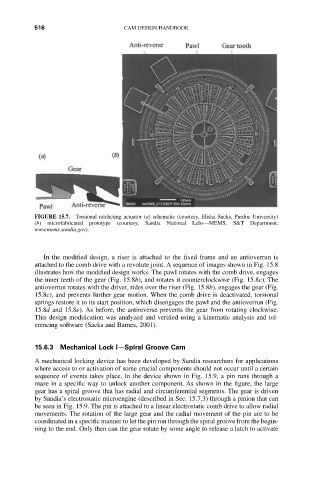
FIGURE 15.7. Torsional ratcheting actuator (a) schematic (courtesy, Elisha Sacks, Purdue University)
(b) microfabricated prototype (courtesy, Sandia National Labs—MEMS, S&T Department,
www.mems.sandia.gov).
In the modified design, a riser is attached to the fixed frame and an antioverrun is
attached to the comb drive with a revolute joint. A sequence of images shown in Fig. 15.8
illustrates how the modified design works. The pawl rotates with the comb drive, engages
the inner teeth of the gear (Fig. 15.8b), and rotates it counterclockwise (Fig. 15.8c). The
antioverrun rotates with the driver, rides over the riser (Fig. 15.8b), engages the gear (Fig.
15.8c), and prevents further gear motion. When the comb drive is deactivated, torsional
springs restore it to its start position, which disengages the pawl and the antioverrun (Fig.
15.8d and 15.8e). As before, the antireverse prevents the gear from rotating clockwise.
This design modification was analyzed and verified using a kinematic analysis and tol-
erencing software (Sacks and Barnes, 2001).
15.6.3 Mechanical Lock I—Spiral Groove Cam
A mechanical locking device has been developed by Sandia researchers for applications
where access to or activation of some crucial components should not occur until a certain
sequence of events takes place. In the device shown in Fig. 15.9, a pin runs through a
maze in a specific way to unlock another component. As shown in the figure, the large
gear has a spiral groove that has radial and circumferential segments. The gear is driven
by Sandia’s electrostatic microengine (described in Sec. 15.7.3) through a pinion that can
be seen in Fig. 15.9. The pin is attached to a linear electrostatic comb drive to allow radial
movements. The rotation of the large gear and the radial movement of the pin are to be
coordinated in a specific manner to let the pin run through the spiral groove from the begin-
ning to the end. Only then can the gear rotate by some angle to release a latch to activate