
Page 529 - Cam Design Handbook
P. 529
THB15 9/19/03 8:03 PM Page 517
CAMS IN MICROELECTROMECHANICAL SYSTEMS 517
(a) (b)
(c) (d )
(e)
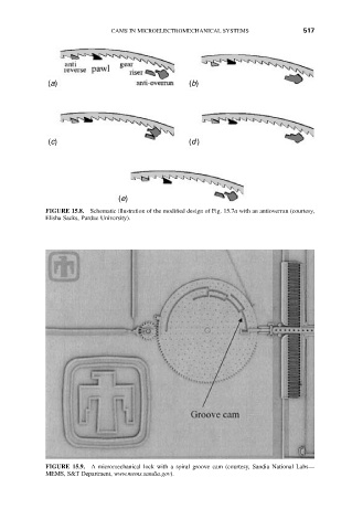
FIGURE 15.8. Schematic illustration of the modified design of Fig. 15.7a with an antioverrun (courtesy,
Elisha Sacks, Purdue University).
FIGURE 15.9. A micromechanical lock with a spiral groove cam (courtesy, Sandia National Labs—
MEMS, S&T Department, www.mems.sandia.gov).