
Page 85 - Cam Design Handbook
P. 85
THB3 8/15/03 12:58 PM Page 73
MODIFIED CAM CURVES 73
Figure 3.8a shows the normalized displacement plot and Fig. 3.8b shows the normalized
velocity plot where h = 1, b = 1.
3.7 MODIFIED SINE CURVE
The modified sine curve (Chen, 1982; Schmidt, 1960) is a combination of quarter sine
wave curves. In terms of its torsional action, the change from positive to negative torque
occurs in over 40 percent of the travel time. This attribute makes this curve attractive as
a choice in moving large masses such as indexing intermittent turrets. Its lower torque and
power demand make the modified sine curve one of the best choices of curves.
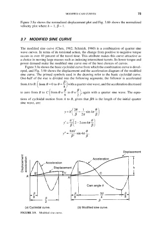
Figure 3.9a shows the basic cycloidal curve from which the combination curve is devel-
oped, and Fig. 3.9b shows the displacement and the acceleration diagram of the modified
sine curve. The primed symbols used in the drawing refer to the basic cycloidal curve.
One-half of the rise is divided into the following segments; the follower is accelerated
Ê b ˆ
from A to B: from = 0 to =q q with a quarter sine wave, and the acceleration decreased
Ë 8 ¯
Ê b b ˆ
q
to zero from B to C from =q to = , again with a quarter sine wave. The equa-
Ë 8 2 ¯
tions of cycloidal motion from A to B, given that b/8 is the length of the initial quarter
sine wave, are:
Ê 2q 1 q ˆ
y = h¢Á - sin 4p ˜
Ë b 2p b ¯
h¢ Ê q ˆ
y¢ = Á22 4p ˜
- cos
b Ë b ¯
8p h¢ q
y¢¢ = sin 4p .
b 2 b
Displacement
Displacement acceleration Acceleration Acceleration h
Displacement
B' h' B C
A'
A
Cam angle q
b b 3b b
8 b 8 4 8
2 b
(a) Cycloidal curve. (b) Modified sine curve.
FIGURE 3.9. Modified sine curve.