Page 89 - Cam Design Handbook
P. 89

THB3  8/15/03  12:58 PM  Page 77

                                     MODIFIED CAM CURVES                    77

            the  beginning  of  motion,  point  B the  end  of  motion,  and  point  P the  mid-stroke
            transition  point.  APB is  the  constant  velocity  line.  M is  the  midpoint  between  A and
            P.  The  sine  amplitudes  are  added  to  the  constant-velocity  line  in  this  true  cycloidal
            case.
               The  modified  cycloidal  curve  was  developed  to  maximize  the  orientation  of  the
            superimposed  sine  wave  amplitude  on  the  straight  line;  see  geometric  construction  in
                                                            b
            Fig. 3.12b. In this figure, a point D equal to 0.57 the distance   is the first chosen and
                                                            2
            then  is  joined  to  M by  a  straight  line.  The  base  of  the  sine  curve  is  then  constructed


                    Distance of Center of Radially Translating Roller  Follower from Center of Cam  4.0
                       5.0
                       4.8


                  y Displacement (in)  4.6
                       4.4
                       4.2


                       3.8
                       3.6
                       3.4
                       3.2

                        0        10      20      30     40     50      60
                                            Cam rotation (deg)
                                              (a) Displacement.
                        18
                        16
                        14
                      y Velocity (in./sec.)  12

                        10

                     .   8
                         6
                         4
                         2

                         0       10      20     30      40     50      60
                                           Cam rotation (deg)
                                              (b) Velocity.
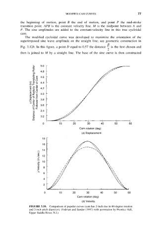
                 FIGURE 3.10.  Comparison of popular curves (cam has 2-inch rise in 60-degree rotation
                 and 3-inch pitch diameter). (Erdman and Sandor (1997) with permission by Prentice Hall,
                 Upper Saddle River, N.J.)
   84   85   86   87   88   89   90   91   92   93   94