Page 92 - Cam Design Handbook
P. 92

THB3  8/15/03  12:58 PM  Page 80

          80                       CAM DESIGN HANDBOOK

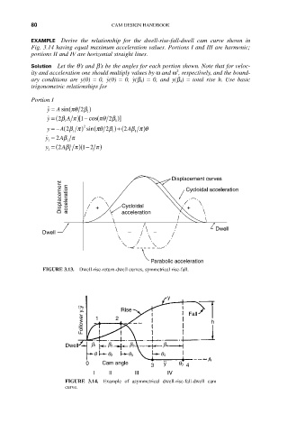
          EXAMPLE Derive  the  relationship  for  the  dwell-rise-fall-dwell  cam  curve  shown  in
          Fig. 3.14 having equal maximum acceleration values. Portions I and III are harmonic;
          portions II and IV are horizontal straight lines.
          Solution Let the q’s and b’s be the angles for each portion shown. Note that for veloc-
                                                      2
          ity and acceleration one should multiply values by w and w , respectively, and the bound-
                                         ˙ y
                                 ˙ y
          ary  conditions  are  y(0)  = 0,  (0)  = 0,  (b 4 )  = 0,  and  y(b 4 )  = total  rise  h.  Use  basic
          trigonometric relationships for
          Portion I
               ˙˙ y =  A sin(pq 2 b  )
                           1
                       p
                         [1
               ˙ y = ( b2  A ) - cos(pq 2 b  )]
                    1               1
               y =- A( bp2  1  )  2  sin(pq 2 b 1 )+ (2 Abp )q
                                         1
               ˙ y = 2 Abp
               1     1
                      2
               y = (2 Abp ) - 2  p )
                         (1
               1      1
                                                     Displacement curves
                   Displacement  acceleration  +  Cycloidal  Cycloidal acceleration

                                                         +
                                      acceleration

                                                                  Dwell
              Dwell                    –       –


                                              Parabolic acceleration
              FIGURE 3.13.  Dwell-rise-return-dwell curves, symmetrical rise-fall.


                                                   y
                          Follower y,y  1  2  Rise        Fall  h


                     Dwell  b 1  b 2    b 3       b 4
                             q   q 2    q 3      q 4
                                                                A
                           0    Cam angle     3   y    q 0  4
                             I    II     III       IV
                     FIGURE  3.14.  Example  of  asymmetrical  dwell-rise-fall-dwell  cam
                     curve.
   87   88   89   90   91   92   93   94   95   96   97