
Page 132 - Carbon Nanotube Fibres and Yarns
P. 132
124 Carbon Nanotube Fibers and Yarns
(A) 50µm (D) 50µm
(B) 5µm (E) 5µm
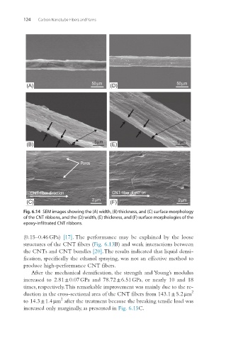
Pores
CNT fiber direction CNT fiber direction
(C) 2µm (F) 2µm
Fig. 6.14 SEM images showing the (A) width, (B) thickness, and (C) surface morphology
of the CNT ribbons, and the (D) width, (E) thickness, and (F) surface morphologies of the
epoxy-infiltrated CNT ribbons.
(0.15–0.46 GPa) [17]. The performance may be explained by the loose
structures of the CNT fibers (Fig. 6.13B) and weak interactions between
the CNTs and CNT bundles [20]. The results indicated that liquid densi-
fication, specifically the ethanol spraying, was not an effective method to
produce high-performance CNT fibers.
After the mechanical densification, the strength and Young’s modulus
increased to 2.81 ± 0.07 GPa and 78.72 ± 6.51 GPa, or nearly 10 and 18
times, respectively. This remarkable improvement was mainly due to the re-
2
duction in the cross-sectional area of the CNT fibers from 143.1 ± 5.2 μm
2
to 14.3 ± 1.4 μm after the treatment because the breaking tensile load was
increased only marginally, as presented in Fig. 6.15C.