
Page 131 - Carbon Nanotube Fibres and Yarns
P. 131
Post-spinning treatments to carbon nanotube fibers 123
two sheets of A4 paper before being mechanically densified into CNT ribbons
by a spatula. Then, 30 wt.% epoxy solution was used to infiltrate the ribbon
structure to improve its mechanical performance.
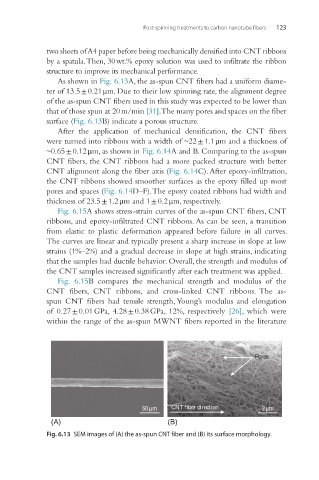
As shown in Fig. 6.13A, the as-spun CNT fibers had a uniform diame-
ter of 13.5 ± 0.21 μm. Due to their low spinning rate, the alignment degree
of the as-spun CNT fibers used in this study was expected to be lower than
that of those spun at 20 m/min [31]. The many pores and spaces on the fiber
surface (Fig. 6.13B) indicate a porous structure.
After the application of mechanical densification, the CNT fibers
were turned into ribbons with a width of ~22 ± 1.1 μm and a thickness of
~0.65 ± 0.12 μm, as shown in Fig. 6.14A and B. Comparing to the as-spun
CNT fibers, the CNT ribbons had a more packed structure with better
CNT alignment along the fiber axis (Fig. 6.14C). After epoxy-infiltration,
the CNT ribbons showed smoother surfaces as the epoxy filled up most
pores and spaces (Fig. 6.14D–F). The epoxy coated ribbons had width and
thickness of 23.5 ± 1.2 μm and 1 ± 0.2 μm, respectively.
Fig. 6.15A shows stress-strain curves of the as-spun CNT fibers, CNT
ribbons, and epoxy-infiltrated CNT ribbons. As can be seen, a transition
from elastic to plastic deformation appeared before failure in all curves.
The curves are linear and typically present a sharp increase in slope at low
strains (1%–2%) and a gradual decrease in slope at high strains, indicating
that the samples had ductile behavior. Overall, the strength and modulus of
the CNT samples increased significantly after each treatment was applied.
Fig. 6.15B compares the mechanical strength and modulus of the
CNT fibers, CNT ribbons, and cross-linked CNT ribbons. The as-
spun CNT fibers had tensile strength, Young’s modulus and elongation
of 0.27 ± 0.01 GPa, 4.28 ± 0.38 GPa, 12%, respectively [26], which were
within the range of the as-spun MWNT fibers reported in the literature
Pores
50µm CNT fiber direction 2µm
(A) (B)
Fig. 6.13 SEM images of (A) the as-spun CNT fiber and (B) its surface morphology.