
Page 133 - Carbon Nanotube Fibres and Yarns
P. 133
Post-spinning treatments to carbon nanotube fibers 125
4 Cross-linked CNT ribbon
4.0 300
Strength
3.5 Young’s modulus
3 250
CNT ribbon 3.0 200
Strength (GPa) 2 Strength (GPa) 2.5 150 Young’s modulus (GPa)
2.0
1 1.5 100
1.0
CNT fiber 50
0.5
0
0.00 0.05 0.10 0.15 0.0 CNT fibers CNT ribbons Cross-linked CNT 0
(A) Strain (B) ribbons
143.07 Cross-sectional area (µm ) 2
Tensile load (cN)
12.08 Failure elongation (%)
11.28
8.45
4.79
3.81 4.01
23.50
14.30
(C) CNT fibers CNT ribbons Cross-linked CNT
ribbons
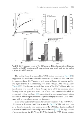
Fig. 6.15 (A) Stress-strain curves of the CNT samples, (B) tensile strength and Young’s
modulus of the CNT samples, and (C) cross-sectional area, tensile load, and elongation
to failure of the CNT samples.
The highly dense structures of the CNT ribbon observed in Fig. 6.14C
suggest that the mechanical densification treatment increased the CNT bun-
dle sizes and inter-CNT contacts, and induced better alignments, leading
to a slight increase in their breaking load from 3.81 ± 0.13 to 4.01 ± 0.1 cN
(Fig. 6.15C). The decrease in the failure strain of the CNT ribbons after the
densification was a result of their stronger inter-CNT interactions. These
findings were in agreement with that of the CNT ribbons densified by
pressurized rolling methods [26], suggesting that mechanical densification
could be an effective posttreatment to produce highly densified CNT struc-
tures with improved mechanical performance.
In the epoxy infiltration treatment, the cross-sectional area of the coated CNT
ribbons increased by more than 60%, as presented in Fig. 6.15C. This result was oppo-
site to the reduction in the cross-sectional area of the CNT fibers after the combined
treatment of liquid densification and polymer infiltration [22, 27]. The large amount
of epoxy coating on the CNTs and CNT bundles of the CNT ribbons was the