
Page 117 - Chalcogenide Glasses for Infrared Optics
P. 117
Characterization of Glass Pr operties 95
Early infrared spectrophotometers were designed to be double-
beam with one used for reference I and the other for the sample I.
0
Optical paths were equal in length and intensity so that the detected
output signals were always I/I . Some instruments used the ratio of
0
the infrared detected electric signals while others, termed optical null
instruments, had a wedge or comb placed in the reference beam to
balance the two signals during the scan while recording the I/I ratio
0
continuously based on the position of the wedge or comb.
The transmission accuracy of commercial instruments under
ideal conditions was usually considered 1 to 2 percent. For absorbing
materials this may be fine. But for low-absorbing, transparent materials,
it means thicker samples 2 cm or more are required for better accuracy.
Unfortunately, a thick sample with a large refractive index increases
the optical path in the sample beam, leading to loss in accuracy. The
instruments in this generation were designed to work with organic
compounds that were thin and had low refractive indexes.
The appearance of Fourier transform instruments was a great
step forward. In this instrument, there is only one beam and it is poly-
chromatic. The beam transmitted through the sample is made to
interfere with itself optically by using a scan mirror producing a pattern
that when analyzed mathematically (Fourier transforms) reveals the
variation in transmitted energy as a function of wavelength. Multiple
scans are used to increase signal-to-noise results. The outcome is
compared to a previously recorded, no-sample same-number-of-scans
reference outcome. The results are displayed in transmission or absorp-
tion terms and printed out after desired additions to the display. Each
scan takes only a few seconds. For poorly transmitting samples,
increased signal-to-noise accuracy may require 50 to 100 scans and the
results averaged, eliminating the influence of noise. The instruments
are very versatile and useful, a real advance in the state of the art.
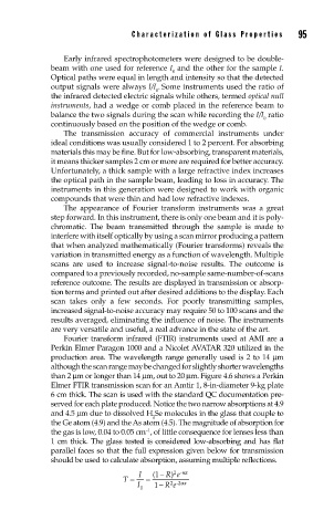
Fourier transform infrared (FTIR) instruments used at AMI are a
Perkin Elmer Paragon 1000 and a Nicolet AVATAR 320 utilized in the
production area. The wavelength range generally used is 2 to 14 µm
although the scan range may be changed for slightly shorter wavelengths
than 2 µm or longer than 14 µm, out to 20 µm. Figure 4.6 shows a Perkin
Elmer FTIR transmission scan for an Amtir 1, 8-in-diameter 9-kg plate
6 cm thick. The scan is used with the standard QC documentation pre-
served for each plate produced. Notice the two narrow absorptions at 4.9
and 4.5 µm due to dissolved H Se molecules in the glass that couple to
2
the Ge atom (4.9) and the As atom (4.5). The magnitude of absorption for
−1
the gas is low, 0.04 to 0.05 cm , of little consequence for lenses less than
1 cm thick. The glass tested is considered low-absorbing and has flat
parallel faces so that the full expression given below for transmission
should be used to calculate absorption, assuming multiple reflections.
2 -α
)
I 1 ( − Re x
T = =
2 -
I 1 − Re 2α x
0