
Page 118 - Chalcogenide Glasses for Infrared Optics
P. 118
96 Cha pte r F o u r
Perkin Elmer
5000 4000 3500 3000 2500 2000 1500 1000 cm –4
100.00
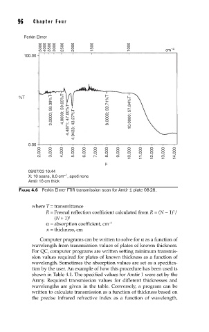
3.0000; 58.39%T 4.0000; 59.65%T 4.4871; 47.00%T 4.9423; 43.27%T 8.0000; 59.71%T 10.0000; 57.84%T
%T
0.00
2.000 3.000 4.000 5.000 6.000 7.000 8.000 9.000 10.000 11.000 12.000 13.000 14.000
µ
08/07/03 10:44
–1
X: 10 scans, 8.0 cm , apod none
Amtir 16 cm thick
FIGURE 4.6 Perkin Elmer FTIR transmission scan for Amtir 1 plate 08-28.
where T = transmittance
2
R = Fresnal reflection coefficient calculated from R = (N − 1) /
(N + 1) 2
α= absorption coefficient, cm −1
x = thickness, cm
Computer programs can be written to solve for α as a function of
wavelength from transmission values of plates of known thickness.
For QC, computer programs are written setting minimum transmis-
sion values required for plates of known thickness as a function of
wavelength. Sometimes the absorption values are set as a specifica-
tion by the user. An example of how this procedure has been used is
shown in Table 4.1. The specified values for Amtir 1 were set by the
Army. Required transmission values for different thicknesses and
wavelengths are given in the table. Conversely, a program can be
written to calculate transmission as a function of thickness based on
the precise infrared refractive index as a function of wavelength,