
Page 84 - Chalcogenide Glasses for Infrared Optics
P. 84
62 Cha pte r T w o
failed even though reactants used were known to form a stable glass.
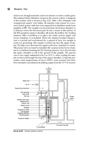
The method failed.Attention turned to the closed system. A diagram
of the system used is shown in Fig. 2.23. After a few attempts with
unsupported quartz vials failed, all samples were placed in evacu-
ated, sealed quartz vials that were supported in chambers made from
graphite or BN. The sample was lowered into the bottom chamber to
a distance where the thermocouple fit into a recess in the bottom of
the BN/graphite support chamber all inside the hollow SiC heating
element. After everything is in place, the entire system, upper and
lower chambers, is evacuated. When the desired reaction tempera-
ture is reached and maintained for a period of time, the sample is
ready for quenching. The sample is pulled up into the upper cham-
ber. The flap valve between the upper and lower chambers is closed.
The pump valve is closed to maintain the vacuum in the lower cham-
ber to avoid heat shocking the SiC heating element. Air is then let into
the upper chamber to aid in the quench of the sample. The quench
rate is very rapid, estimated to be 5 to 10°C/s. After cooling the sam-
ple is removed through the top of the upper chamber. Using this pro-
cedure, melt temperatures of up to 1700°C were reached and held.
First attempts concentrated on making a glass from the Ti-V-Te system.
FIGURE 2.23 Closed system reactor.