
Page 99 - Chalcogenide Glasses for Infrared Optics
P. 99
Glass Pr oduction 77
to results from the standard production. Also shown are results of
absorption at 10.6 µm, determined by measuring the heat rise in a sample
while transmitting a CO laser beam of known intensity. The measure-
2
ment, termed laser calorimetry, was applied to the same glass by TI, the
Naval Research Laboratory, and the Catholic University. Results were
−1
from 0.012 to 0.007 cm . A correlation between Si content and absorp-
tion at 10.6 and 9.4 µm was found for both TI 1173 and TI 20. The
10.6-µm results are shown in Fig. 3.5. The X in the figure is for the one
TI 20 glass tested. Obviously, the reactant purification step would sub-
stantially improve quality and the transmission if adopted into the
production of these two infrared-transmitting chalcogenide glasses.
3.4 Open Casting Methods
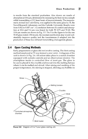
Early preparations of glass did not involve casting. The first casting
method employed at TI was termed a pour caster. A diagram of the
unit is shown in Fig. 3.6. All action takes place in a sealed chamber
equipped with outside controls and an observation window. The
atmosphere inside is controlled flow of inert gas. The glass to
be cast is placed in the crucible and moved into the melting furnace
where it can be melted and stirred. After mixing and reaching of the
proper temperature, the stirring is stopped, allowing any bubbles to
Stirrer
Melting furnace
Crucible
Mold
Window
Controlled atmosphere
chamber
Mold heater
FIGURE 3.6 Diagram of the TI pour glass casting unit.