
Page 100 - Chalcogenide Glasses for Infrared Optics
P. 100
78 Cha pte r T h ree
rise to the surface. The crucible is moved from the furnace and
tilted, and the glass is poured into the mold. The glass is cooled
and then annealed. Plates 5 × 5 in up to 5 × 7 in were produced.
The homogeneity of glass thus produced was not good because of
excess striae.
A second casting method was developed in which the melted
glass in the crucible was allowed to flow through a bottom hole tube
into a mold directly below. This method was referred to as the bottom
hole caster. Initially, the bottom hole was plugged by the first glass to
melt. When casting time arrived, a heater around the bottom tube
was turned on, and the glass plug melted so the glass flowed freely
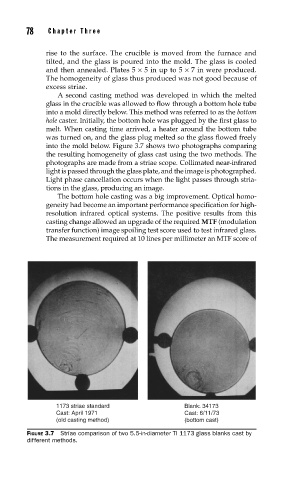
into the mold below. Figure 3.7 shows two photographs comparing
the resulting homogeneity of glass cast using the two methods. The
photographs are made from a striae scope. Collimated near-infrared
light is passed through the glass plate, and the image is photographed.
Light phase cancellation occurs when the light passes through stria-
tions in the glass, producing an image.
The bottom hole casting was a big improvement. Optical homo-
geneity had become an important performance specification for high-
resolution infrared optical systems. The positive results from this
casting change allowed an upgrade of the required MTF (modulation
transfer function) image spoiling test score used to test infrared glass.
The measurement required at 10 lines per millimeter an MTF score of
1173 striae standard Blank: 34173
Cast: April 1971 Cast: 6/11/73
(old casting method) (bottom cast)
FIGURE 3.7 Striae comparison of two 5.5-in-diameter TI 1173 glass blanks cast by
different methods.