
Page 162 - Chemical Process Equipment - Selection and Design
P. 162
134 FLUID TRANSPORT EQUIPMENT
PER CENT OF CAPACITY bT MAXIMUM EFFlClENCV
FS3 CENT OF CbPAClTY AT MAXIMUM EFFICIENCY
(a) (b)
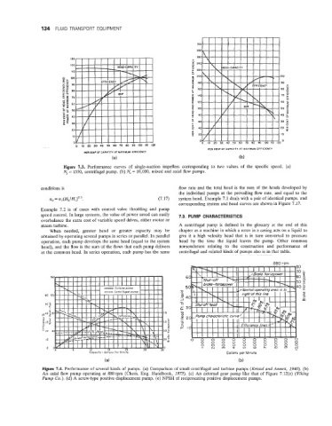
Figure 7.3. Performance curves of single-suction impellers corresponding to two values of the specific speed. (a)
N, = 1550, centrifugal pump. (b) N, = 10,000, mixed and axial flow pumps.
conditions is flow rate and the total head is the sum of the heads developed by
the individual pumps at the prevailing flow rate, and equal to the
nz = n,(Hz/H,)o.5. (7.17) system head. Example 7.1 deals with a pair of identical pumps, and
corresponding system and head curves are shown in Figure 7.17.
Example 7.2 is of cases with control valve throttling and pump
speed control. In large systems, the value of power saved can easily 7.8. PUMP CHARACTERISTICS
overbalance the extra cost of variable speed drives, either motor or
steam turbine. A centrifugal pump is defined in the glossary at the end of this
When needed, greater head or greater capacity may be chapter as a machine in which a rotor in a casing acts on a liquid to
obtained by operating several pumps in series or parallel. In parallel give it a high velocity head that is in turn converted to pressure
operation, each pump develops the same head (equal to the system head by the time the liquid leaves the pump. Other common
head), and the flow is the sum of the flows that each pump delivers nomenclature relating to the construction and performance of
at the common head. In series operation, each pump has the same centrifugal and related kinds of pumps also is in that table.
Capacity- Gallons Per Minute
(a) (b)
Figure 7.4. Performance of several kinds of pumps. (a) Comparison of small centrifugal and turbine pumps (Kristal and Annett, 1940). (b)
An axial flow pump operating at 880rpm (Chem. Eng. Handbook, 1973). (c) An external gear pump like that of Figure 7.12(e) (Viking
Pump Co.). (d) A screw-type positive displacement pump. (e) NPSH of reciprocating positive displacement pumps.