
Page 163 - Chemical Process Equipment - Selection and Design
P. 163
IO0 50
80 40
E L
El
GO 30
a
t 0
L
UI
0 0
," 40 20 =
V
20 10
1.000 2.000 3.CSO 4.000
DISCW'IRGE PRESSURE La/'Nz
0 0
0 60 I20 I80 240 300
Discharge pressure. psi
(4
PLUNGER
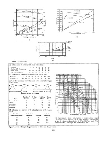
Figure 7.4--(conrinued)
:a) Efficiencies as % of those with direct piston drive:
Stroke, in 5 8 10 20 30 40 50
Crank-and-flywheel plump 87 88 90 92
Piston pump 60 70 74 84 86 88 90
High-pressure pump 55 64 67 76 78 80 81
:b) Efficiencies of crankshaft-driven pumps of various sizes:
Water HP 3 5 10 20 30 50 75 100 200
Efficiency(%) 55 65 72 77 80 83 85 86 88
:c) % of flow above and below the mean; curve is shown for triplex
iouble-acting :
e No. B -4 k- Cylinder No. 3 --+l
Cylinder
cylinder No. z
Number of % above % below Plunger
Plungers Mean Mean Phase
Duplex (double) 2 24 22 180"
Triplex 3 6 17 120"
Quaduplex 4 11 22 90"
Quintaplex 5 2 5 72"
Sextuplex 6 5 9 60"
(d) Efficiency as a function of % reduced pressure or % reduced
speed:
% Full-Laad Mechanical Mechanical
Developed Pressure Efficiency % Speed Efficiency
20 82 44 93.3 (e) Approximate steam consumption of reciprocating pumps
40 88 50 92.5 (Hydraulic Institute, Cleveland, OH, 1957). Example: A pump with
60 90.5 73 92.5 a 10 x 10 cylinder and developing 33 HP at 90 ft/min needs 73 lb
80 92 100 92.5 steam/water HP. The 50 fpm line is a reference line.
100 92.5
Figure 7.5. Data relating to the performance of piston and plunger pumps.
135