Page 164 - Chemical Process Equipment - Selection and Design
P. 164

136  FLUID TRANSPORT  EQUIPMENT


                   EXAMPLE                                             Clearly  the  performance  curves  are  well  within  the  recorn-
                          7.3
                   Check  of  Some  Performance  Curves  with  the  Concept  of   mended upper limits of specific speed.
                   Specific Speed                                   (b)  The manufacturer’s recommended NPSH of the pump of Figure
                (a)  The  performance  of  the  pump  of  Figure  7.7(h)  with  an Sin.   7.7(c) with an 8 in. impeller will be checked against values from
                   impeller  will  be  checked  by  finding  its  specific  speed  and   Eq. (7.15) with S = 7900:
                   comparing  with  the  recommended  upper  limit  from  Figure
                   7.6(b). Use Eq. (7.12) for N,                           Q (gprn)       100    150    200
                                                                           H (fi)         490    440    300
                        Q (gpm)         100    200   300                   NPSH (rnfgr)    10    18     35
                        H (ft)          268    255   225                   NPSH [Eq.  (7.1511   7.4   9.7   11.8
                        N, (calcd)      528    776   1044
                        N, [Fig. 7.10(a)l   2050   2150   2500         The manufacturer’s recommended NPSHs are conservative.
                        NPSH              5     7     13


                                          H  total head, f t (first stage)   H= total head,ft  (first stoge)
                                                   (a)                                (b)
                                 cn
                                 2  4,000
                                 a
                                 0’   3,500
                                 0
                                 5 3,000
                                 3
                                 -  2,500
                                 .-
                                 m
                                 t
                                 VI
                                 6  2,000
                                 L
                                    1,500
                                  VI
                                 2,
                                 .on.
                                 g g  1,000
                                 BQ 900
                                 .u &
                                 c= 800
                                 XK
                                     700000 0     0  00 000 0 0
                                        gscmg  g$   $ma,mon  N
                                           H= total heod,ft (first stage)    H= total head, ft(first stage)
                                                   (C)                                 (d)
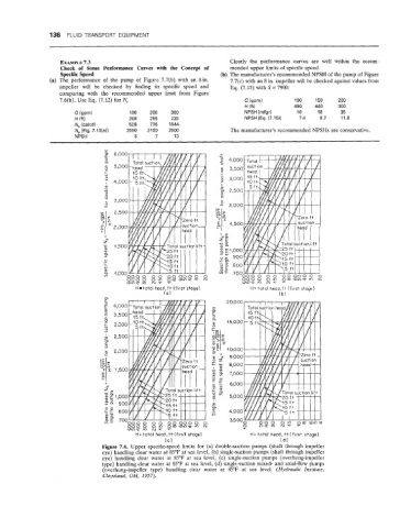
                                Figure 7.6.  Upper  specific-speed limits for  (a) double-suction pumps (shaft through impeller
                                eye) handling clear water at 85°F at sea level, (b) single-suction pumps (shaft through impeller
                                eye)  handling clear  water  at  85°F  at  sea level,  (c)  single-suction pumps  (overhung-impeller
                                type) handling clear water at 85°F at sea level, (d) single-suction mixed- and axial-flow pumps
                                 (overhung-impeller type)  handling  clear  water  at  85°F  at  sea  level.  (Hydraulic  Institute,
                                 Cleveland,  OH, 1957).
   159   160   161   162   163   164   165   166   167   168   169