
Page 165 - Chemical Process Equipment - Selection and Design
P. 165
7.3 PUMP CHARACTERISTICS 137
U. S GALLONS PER MINUTE
b)
(C)
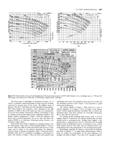
Figure 7.7. Characteristic curves of centrifugal pumps when operating on water at 85°F (Allis Chalmers eo.). (a) Single suction, 1750 rpm. (b)
The pump of (a) operated at 3500 rpm. (c) Multistage, single suction, 3550 rpm.
The basic types of centrifugals are illustrated in Figure 7.9. A centrifugal vane action; the propeller confers high rates of flow but
volute is a gradually expanding passage in which velocity is partially the developed pressure is low. Figure 7.3(b) represents a typical
converted to pressure head at the outlet. The diffuser vanes of axial pump performance.
Figures 7.9(b) and 7.10(d) direct the flow smoothly to the periphery. The turbine impeller of Figure 7.1Q(h) rotates in a case of
The volute design is less expensive, more amenable to use with uniform diameter, as in Figure 7.12(j). As Figure 7.4(a) demon-
impellers of different sizes in the same case, and, as a consequence, strates, turbine pump performance resembles that of positive dis-
by far the most popular construction. Diffuser construction is used placement types. Like them, turbines are essentially self-priming,
to a limited extent in some high pressure, multistage machines. The that is, they will not vapor bind.
double suction arrangement of Figure 7.91(d) has balanced axial All rotating devices handling fluids require seals io prevent
thrust and is favored particularly for severe duty and where the leakage. Figure 7.13 shows the two common methods that are used:
lowered NPSH is an advantage. Multistage pumps, however, are stuffing boxes or mechanical seals. Stuffing boxes employ a soft
exclusively single suction. packing that is compressed and may be lubricated with the pump
Some of the many kinds of impellers are shown in Figure 7.10. liquid or with an independent source. In mechanical seals, smooth
For clear liquids, some form of closed impeller [Figure 7.1Q(c)] is metal surfaces slide on each other, and are lubricated with a very
favored. They may differ in width and number and curvature of the small leakage rate of the pump liquid or with an independent liquid.
vanes, and of course in the primary dimension, the diameter. Performance capability of a pump is represented on diagrams
Various extents of openness of impellers, [Figs. 7.10(a) and (b)] are like those of Figure 7.7. A single point characterization often is
desirable when there is a possibility of clogging as with slurries or made by stating the performance at the peak efficiency. For
pulps. The impeller of Figure 7.1Q(e) has both axial propeller and example, the pump of Figure 7.7(c) with a 9 in. impeller is called a