
Page 246 - Chemical Process Equipment - Selection and Design
P. 246
216 HEAT TRANSFER AND HEAT EXCHANGERS
TABLE 8.16-(continoed)
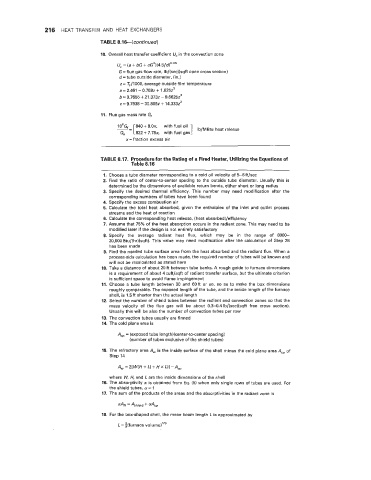
10. Overall heat transfer coefficient U, in the convection zone
U, = (a + bG + ~G’)(4.5/d)~’*~
G= flue gas flow rate, Ib/(sec)(sqft open cross section)
d= tube outside diameter, (in.)
z= T,/IOOO, average outside film temperature
a = 2.461 - 0,7592 + 1.6252‘
b= 0.7655 + 21.3732 - 9.66252’
C= 9.7938 - 30.8092 + 14.3332*
11. Flue gas mass rate Gf
with fuel oil ]
840 + 8.0x,
822 + 7.78x, with fuel gas Ib/MBtu heat release
x= fraction excess air
TABLE 8.17. Procedure for the Rating of a Fired Heater, Utilizing the Equations of
Table 8.16
1. Choose a tube diameter corresponding to a cold oil velocity of 5-6ft/sec
2. Find the ratio of center-to-center spacing to the outside tube diameter. Usually this is
determined by the dimensions of available return bends, either short or long radius
3. Specify the desired thermal efficiency. This number may need modification after the
corresponding numbers of tubes have been found
4. Specify the excess combustion air
5. Calculate the total heat absorbed, given the enthalpies of the inlet and outlet process
streams and the heat of reaction
6. Calculate the corresponding heat release, (heat absorbed)/efficiency
7. Assume that 75% of the heat absorption occurs in the radiant zone. This may need to be
modified later if the design is not entirely satisfactory
8. Specify the average radiant heat flux, which may be in the range of 8000-
20,000 Btu/(hr)(sqft). This value may need modification after the calculation of Step 28
has been made
9. Find the needed tube surface area from the heat absorbed and the radiant flux. When a
process-side calculation has been made, the required number of tubes will be known and
will not be recalculated as stated here
10. Take a distance of about 20 ft between tube banks. A rough guide to furnace dimensions
is a requirement of about 4cuft/sqft of radiant transfer surface, but the ultimate criterion
is sufficient space to avoid flame impingement
11. Choose a tube length between 30 and 60ft or so, so as to make the box dimensions
roughly comparable. The exposed length of the tube, and the inside length of the furnace
shell, is 1.5ft shorter than the actual length
12. Select the number of shield tubes between the radiant and convection zones so that the
mass velocity of the flue gas will be about 0.3-0.4Ib/(sec)(sqft free cross section).
Usually this will be also the number of convection tubes per row
13. The convection tubes usually are finned
14. The cold plane area is
A,, = (exposed tube length)(center-to-center spacing)
(number of tubes exclusive of the shield tubes)
15. The refractory area 4, the inside surface of the shell minus the cold plane area A,, of
is
Step 14
4, = 2[ W(H + L) + H X L)] -A,
where W, H, and L are the inside dimensions of the shell
16. The absorptivity 01 is obtained from Eq. (5) when only single rows of tubes are used. For
the shield tubes, 01 = 1
17. The sum of the products of the areas and the absorptivities in the radiant zone is
= Ahield + OIAcp
18. For the box-shaped shell, the mean beam length L is approximated by
L = $(furnace volume)’”