
Page 250 - Chemical Process Equipment - Selection and Design
P. 250
220 HEAT TRANSFER AND HEAT EXCHANGERS
1- I
'I .IO
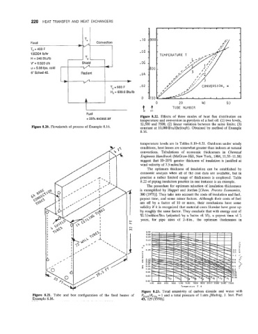
Feed Convection
t/
To = 400 F . oa
195394 Ib/hr
H = 248 BWlb TLl
V' = 0.920 cfs Shield .06
u = 5.08 fps, cold vn 4-
6 Sched 40. Radiant .04
T2 = 900 F .02
H, = 609.6 Btullb
0
0 20 40 60
tf TUBE NUMBER
xt-
Fuel
+ 25% excess air Figure 8.22. Effects of three modes of heat flux distribution on
temperature and conversion in pyrolysis of a fuel oil: (1) two levels,
12,500 and 7500; (2) linear variation between the same limits; (3)
Figure 8.20. Flowsketch of process of Example 8.16. constant at 10,000 Btu/(hr)(sqft). Obtained by method of Example
8.16.
temperature levels are in Tables 8.19-8.21. Outdoors under windy
conditions, heat losses are somewhat greater than indoors at natural
convections. Tabulations of economic thicknesses in Chemical
Engineers Handbook (McGraw-Hill, New York, 1984, 11.55-11.58)
suggest that 10-20% greater thickness of insulation is justified at
wind velocity of 7.5 miles/hr.
The optimum thickness of insulation can be established by
economic analysis when all of the cost data are available, but in
practice a rather limited range of thicknesses is employed. Table
8.22 of piping insulation practice in one instance is an example.
The procedure for optimum selection of insulation thicknesses
is exemplified by Happel and Jordan [Chem. Process Economics,
380 (1975)l. They take into account the costs of insulation and fuel,
payout time, and some minor factors. Although their costs of fuel
are off by a factor of 10 or more, their conclusions have some
validity if it is recognized that material costs likewise have gone up
by roughly the same factor. They conclude that with energy cost of
$2.5/millionBtu (adjusted by a factor of lo), a payout time of 2
years, for pipe sizes of 2-8in., the optimum thicknesses in
0.70
0.60
0.50
0 40
0.30
w
0.20 3.0
L 2.0 n
1.2 --
: 8rl% 0.8 m" 0
0.6 +a-
0.07
0.06 0.4 *=
L1) 0.05 If9
0.06
0.03 0.08
0.06
0.02
LOO 600 800 1000 1200 lL00 1600 I800 20GO 2200 2L00 2600
Temperature T, K
Figure 8.23. Total emissivity of carbon dioxide and water with
Figure 8.21. Tube and box configuration of the fired heater of PH2,/Pc,, = 1 and a total pressure of 1 atm [Haduig, J. Inst. Fuel
Example 8.16. 43, 129 (1970)].