
Page 306 - Chemical Process Equipment - Selection and Design
P. 306
270 DRYERS AND COOLING TOWERS
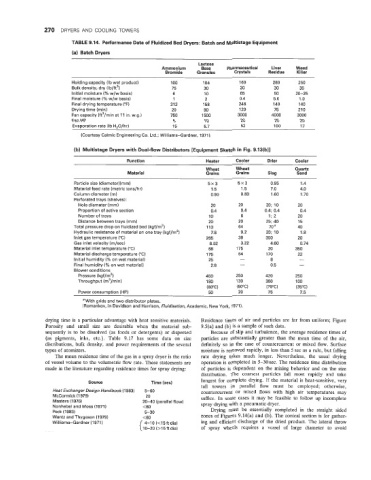
TABLE 9.14. Performance Data of Fluidized Bed Dryers: Batch and Multistage Equipment
(a) Batch Dryers
Lactose
Ammonium Base Pharmaceutical Liver Weed
Bromide Granules Crystals Residue Killer
Holding capacity (Ib wet product) 100 104 160 280 250
Bulk density, dry (lb/ft3) 75 30 20 30 35
Initial moisture (% w/w basis) 6 10 65 50 20-25
Final moisture (% w/w basis) 1 2 0.4 5.0 1 .o
Final drying temperature (“F) 21 2 158 248 140 140
Drying time (min) 20 90 120 75 21 0
Fan capacity (ft3/min at 11 in. w.g.) 750 1500 3000 4000 3000
Fan HP 5 10 20 25 20
Evaporation rate (Ib H,O/hr) 15 5.7 52 100 17
(Courtesy Calmic Engineering Co. Ltd.; Williams-Gardner, 1971 1.
(b) Multistage Dryers with Dual-flow Distributors [Equipment Sketch in Fig. 9.13(b)]
Function Heater Cooler Drier Cooler
Wheat Wheat Quartz
Material Grains Grains Slag Sand
Particle size (diameter)(mm) 5x3 5x3 0.95 1.4
Material feed rate (metric tons/hr) 1.5 1.5 7.0 4.0
Column diameter (m) 0.90 0.83 1.60 1.70
Perforated trays (shelves):
Hole diameter (mm) 20 20 20; 10 20
Proportion of active section 0.4 0.4 0.4; 0.4 0.4
Number of trays 10 6 1; 2 20
Distance between trays (mm) 20 20 25; 40 15
Total pressure drop on fluidized bed (kgf/mz) 113 64 70 a 40
Hydraulic resistance of material on one tray (kgf/m2) 7.8 9.2 20; 10 1.8
Inlet gas temperature (“C) 265 38 300 20
Gas inlet velocity (m/sec) 8.02 3.22 4.60 0.74
Material inlet temperature (“C) 68 175 20 350
Material discharge temperature (“C) 175 54 170 22
Initial humidity (% on wet material) 25 - 8 -
Final humidity (% on wet material) 2.8 - 0.5 -
Blower conditions
Pressure (kgf/m*) 450 250 420 250
Throughput (m3/min) 180 130 360 100
(80°C) (50°C) (70°C) (35°C)
Power consumption (HP) 50 20 75 7.5
a With grids and two distributor plates.
(Romankov, in Davidson and Harrison, Fluidisation, Academic, New York, 1971).
drying time is a particular advantage with heat sensitive materials. Residence times of air and particles are far from uniform; Figure
Porosity and small size are desirable when the material sub- 9.5(a) and (b) is a sample of such data.
sequently is to be dissolved (as foods or detergents) or dispersed Because of slip and turbulence, the average residence times of
(as pigments, inks, etc.). Table 9.17 has some data on size particles are substantially greater than the mean time of the air,
distributions, bulk density, and power requirements of the several definitely so in the case of countercurrent or mixed flow. Surface
types of atomizers. moisture is removed rapidly, in less than 5 sec as a rule, but falling
The mean residence time of the gas in a spray dryer is the ratio rate drying takes much longer. Nevertheless, the usual drying
of vessel volume to the volumetric flow rate. These statements are operation is completed in 5-30 sec. The residence time distribution
made in the literature regarding residence times for spray drying: of particles is dependent on the mixing behavior and on the size
distribution. The coarsest particles fall most rapidly and take
longest for complete drying. If the material is heat-sensitive, very
Source Time (sec)
tall towers in parallel flow must be employed; otherwise,
Heat Exchanger Design Handbook (1983) 5-60 countercurrent or mixed flows with high air temperatures may
McCormick (1979) 20 suffice. In some cases it may be feasible to follow up incomplete
Masters (1976) 20-40 (parallel flow) spray drying with a pneumatic dryer.
Nonhebel and Moss (1971) 160 Drying must be essentially completed in the straight sided
Peck (1983) 5-30
Wentz and Thygeson (1979) zones of Figures 9.14(a) and (b). The conical section is for gather-
Williams-Gardner (1971 ) 4-10 (<15ftdia) ing and efficient discharge of the dried product. The lateral throw
10-20 (>15ftdia) of spray wheels requires a vessel of large diameter to avoid