
Page 301 - Chemical Process Equipment - Selection and Design
P. 301
9.9. FLUIDIZED BED DRYERS 265
Recirculation
duct -Stack
Expansion
I bellows
ID fan
I
Change over flap
1
3ted rnoterial
mixer
2 Bottom bend . ~ . ~
hammer mill
Combustion chamber
(b)
I. Fan
2. Ring duct
3. Manifold
4. Injector
5. Air outlet
6. Feeder
7. Filter
8. Heater
9. Cyclone 7
IO. Disintegrator
/I. Bag filter
12. Discharge
(C)
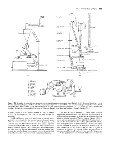
Figure 9.12. Examples of pneumatic conveying dryers; corresponding performance data are in Table 9.13. (a) Raymond flash dryer, with a
hammer mill for disintegrating the feed and with partial recycle of product (Raymond Division, Combustion Engineering). (b) Buttner-Rosin
pneumatic dryer with separate recycle and disintegration of large particles (Rosin Engineering Ltd.). (c) Berks ring dryer; the material
circulates through the ring-shaped path, product is withdrawn through the cyclone and bag filter (Penmalt Chemical Co.).
complete drying is a recirculation scheme like that of Figure One way of drying solutions or pastes under fluidizing
9.131(e). In batch opelration the time cain be made as long as conditions is that of Figure 9.13(g). Here the fluidized mass is of
necessary. auxiliary spheres, commonly of plastic such as polypropylene, into
Stable fluidnzation requires a distribution of particle sizes, which the solution is sprayed. The feed material deposits uniformly
preferably in the range of a few hundred microns. Normally a size on the spheres, dries there, and then is knocked off automatically as
of 4mm or so is considered an upper limit, but the coal dryers of it leaves the drier and leaves the auxiliary spheres behind. When a
Tables 9.15(a) and (b) accommodate sizes up to 0.5in. Large and mass of dry particles can be provided to start a fluidized bed drying
uniformly sized particles, such as grains, are dried successfully in process, solutions or pastes can be dried after deposition on the
spouted beds [Fig. 9.13(f)]: Here a high velocity gas stream entrains seed material as on the auxiliary spheres. Such a process is
the solid upward at the axis and releases it at the top for flow back employed, for instance, for growing fertilizer granules of desired
through the annulus. Some operations do without the mechanical larger sizes, and has largely replaced rotary dryers for this purpose.
draft tube shown but employ a naturally formed central channel. A few performance data of batch fluid dryers are in Table