
Page 298 - Chemical Process Equipment - Selection and Design
P. 298
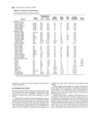
262  DRYERS AND  COOLING  TOWERS
                   TABLE 9.12. Performance of Drum Dryers
                   (a) Single, Double drum and Vacuum Drums

                                                       Moisture Content,
                                                        (% Wet Basis)   Steam    Drum    Feed    Capacity
                                              Method                  Pressure,   Speed   Temp.   [Ib product/   Vacuum
                            Material          of  Feed   Feed   Product   (Ib/sq in.)   (rpm)   (“F)   (hr)(sq R)]   (in. Hg)
                   Double-drum dryer
                     Sodium sulfonate        trough   53.6     6.4       63      8;      164      7.75
                     Sodium sulfate          trough   76.0     0.06      56      7       150      3.08
                     Sodium phosphate        trough   57.0     0.9       90      9       180      8.23
                     Sodium acetate         trough    39.5     0.44      70      3       205       1.51
                     Sodium acetate         trough    40.5     10.03     67      8       200      5.16
                     Sodium acetate          trough   63.5     9.53      67      8       170      3.26
                   Single-drum dryer
                     Chromium sulfate        spray film   48.5   5.47    50      5        -       3.69
                     Chromium sulfate        dip      48.0     8.06      50      4        -        1.30
                     Chromium sulfate        pan      59.5     5.26      24      2;      158       1.53
                     Chromium sulfate        splash   59.5     4.93      55      1;      150      2.31
                     Chromium sulfate        splash    59.5    5.35      53      4;      154       3.76
                     Chromium sulfate        dip       59.5    4.57      53      5;      153      3.36
                     Vegetable glue          pan       60-70   10-12    20-30    6-7      -       1-1.6
                     Calcium arsenate        slurry   75-77   0.5-1.0   45-50    3-4      -       2-3
                     Calcium carbonate       slurry   70        0.5      45      2-3      -      1.5-3
                   Twin-drum dryer
                     Sodium sulfate          dip       76      0.85      55      7       110       3.54
                     Sodium sulfate          top       69      0.14      60      9;      162      4.27
                     Sodium sulfate          top       69      5.47      32      9;      116       3.56
                     Sodium sulfate          splash    71      0.10      60      6       130      4.30
                     Sodium sulfate          splash   71.5     0.17      60     12       140       5.35
                     Sodium sulfate          splash    71.5    0.09      60      10      145       5.33
                     Sodium phosphate        splash    52.5    0.59      58      5;      208       8.69
                     Sodium phosphate        dip       55      0.77      60      54      200       6.05
                     Sodium sulfonate        top       53.5    8-10      63      8;      172      10.43
                   Vacuum single-drum dryer
                     Extract                 pan       59      7.75      35      8        -        4.76     27.9
                     Extract                 Pan       59      2.76      35      6        -        1.92     27.9
                     Extract                 Pan       59      2.09      36      4        -        1.01    atmos.
                     Extract                 pan       56.5     1.95     35      74       -        3.19     22.7
                     Extract                 pan       56.5     1.16     50      22       -        0.75    atmos.
                     Skim milk               pan       65      2-3      10-12    4-5      -      2.5-3.2
                     Malted milk             Pan       60      2        30-35    4-5      -        2.6
                     Coffee                  pan       65      2-3      5-10     1-1;     -      1.6-2.1
                     Malt extract            spray film   65   3-4      3-5     0.5-1.0   -      1.3-1.6
                     Tanning extract         pan       50-55   8-10     30-35     8-10    -      5.3-6.4
                     Veoetable alue          oan       60-70   10-12    15-30     5-7     -       2-4
                      (Perrys Chemical Engineers Handbook,  McGraw-Hill, 1950 edition).


                 calculation of  residence  time  when  assumptions are  made  about   collecting fines,  and  a  heater  and  blower  for  the  gaseous  drying
                 terminal temperatures.                              medium.
                                                                        Much ingenuity has been applied to the design of  fluidized bed
                 9.9.  FLUIDIZED BED  DRYERS                         drying. Many  different arrangements of  equipment are  illustrated
                                                                     and  described  in  the  comprehensive  book  of  Kro11  (1978)  for
                 Free flowing granular materials that require  relatively short drying   instance. Figure 9.13(a) depicts the basic kind of  unit and the other
                 times are particularly suited to  fluidized bed  drying. When longer   items  are  a  few  of  the  many  variants.  Tables  9.14  and  9.15  are
                 drying  times  are  necessary,  multistaging,  recirculation  or  batch   selected performance data.
                 operation  of  fluidized beds  still may  have  advantages over  other   Shallow beds are easier to maintain in stable fluidization and of
                 modes.                                              course exert a smaller load on the air blower. Pressure drop in the
                    A fluidized bed is made up of  a mass of particles buoyed up out   air  distributor  is  approximately  1 psi  and  that  through  the  bed
                 of  permanent contact with each other by  a flowing fluid. Turbulent   equals the weight of  the bed per unit cross section. Some pressure
                 activity in such a bed promotes high rates of  heat and mass transfer   drop data are shown in Table 9.14.  The cross section is determined
                 and  uniformity of  temperature  and  composition throughout.  The   by the gas velocity needed for fluidization as will be described. It is
                 basic system includes a solids feeding device, the fluidizing chamber   usual to allow 3-6  ft of  clear height between the top of  the bed and
                 with a perforated distributing plate for the gas, an overflow duct for   the  air  exhaust  duct.  Fines that  are  entrained  are  collected in  a
                 removal  of  the  dry  product,  a  cyclone  and  other  equipment  for   cyclone and blended with the main stream since they are very dry