
Page 304 - Chemical Process Equipment - Selection and Design
P. 304
268 DRYERS AND COOLING TOWERS
where Gmf is in Ib/(hr)(sqft), pg and ps are densities of the gas and 9.10. SPRAY DRYERS
solid (lb/cuft), Dp is the particle diameter (in.), and p is the gas
viscosity (cP). In view of the wide scatter of the data on which this Suitable feeds to a spray dryer are solutions or pumpable pastes and
correlation is based, shown on Figure 6.14(f), it appears advisable slurries. Such a material is atomized in a nozzle or spray wheel,
to find the fluidization velocity experimentally for the case in hand. contacted with heated air or flue gas and conveyed out of the
Although it is embarrassing again to admit the fact, equipment with a pneumatic or mechanical type of conveyor.
unfortunately all aspects of fluidized bed drying must be established Collection of fines with a cyclone separator or filter is a major
with pilot plant tests. The wide ranges of performance parameters aspect of spray dryer operation. Typical equipment arrangements
in Tables 9.14 and 9.15 certainly emphasize this conclusion. A and flow patterns are shown in Figure 9.14.
limited exploration of air rates and equipment size can be made on The action of a high speed spray wheel is represented by Figure
the basis of a drying rate equation and fluidization correlations from 9.14(e); the throw is lateral so that a large diameter vessel is required
the literature. This is done in Example 9.9. A rough approximation with this form of atomization, as shown in Figure 9.14(a). The flow
of a drying rate equation can be based on through circulation drying from nozzles is largely downward so that the dryer is slimmer and
of the granular material on a tray, with gas flow downward. taller. Parallel flow of air and spray downward is the most common
I wet Inateria'
inlet 1 DV material
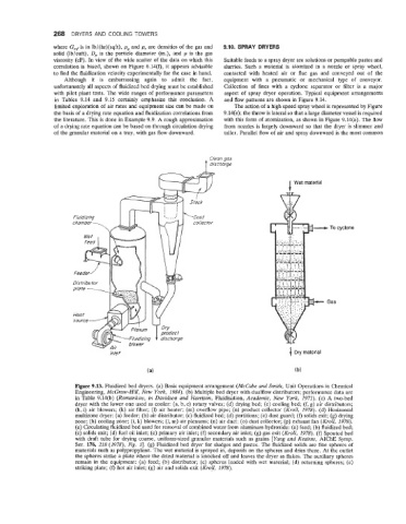
Figure 9.13. Fluidized bed dryers. (a) Basic equipment arrangement (McCabe and Smith, Unit Operations in Chemical
Engineering, McGraw-Hill, New York, 1984). (b) Multiple bed dryer with dualflow distributors; performance data are
in Table 9.14(b) (Romankov, in Davidson and Harrison, Fluidisation, Academic, New York, 1971). (c) A two-bed
dryer with the lower one used as cooler: (a, b, c) rotary valves; (d) drying bed; (e) cooling bed; (f, g) air distributors;
(h,i) air blowers; (k) air filter; (1) air heater; (m) overflow pipe; (n) product collector (Kroll, 1978). (d) Horizontal
multizone dryer: (a) feeder; (b) air distributor; (c) fluidized bed; (d) partitions; (e) dust guard; (f) solids exit; (g) drying
zone; (h) cooling zone; (i, k) blowers; (1, m) air plenums; (n) air duct; (0) dust collector; (p) exhaust fan (Kroll, 1978).
(e) Circulating fluidized bed used for removal of combined water from aluminum hydroxide: (a) feed; (b) fluidized bed;
(c) solids exit; (d) fuel oil inlet; (e) primary air inlet; (f) secondary air inlet; (g) gas exit (Kroll, 1978). (f) Spouted bed
with draft tube for drying coarse, uniform-sized granular materials such as grains [Yang and Keairns, AIChE Symp.
Ser. 176, 218 (1978), Fig. 11. (8) Fluidized bed dryer for sludges and pastes. The fluidized solids are fine spheres of
materials such as polypropylene. The wet material is sprayed in, deposits on the spheres and dries there. At the outlet
the spheres strike a plate where the dried material is knocked off and leaves the dryer as flakes. The auxiliary spheres
remain in the equipment: (a) feed; (b) distributor; (c) spheres loaded with wet material; (d) returning spheres; (e)
striking plate; (f) hot air inlet; (8) air and solids exit (Kroll, 1978).