
Page 32 - Chemical Process Equipment - Selection and Design
P. 32
1.10. STEAM AND POWER SUPPLY 9
1.10. STEAM AND POWER SUPPLY
For smaller plants or for supplementary purposes, steam and power
(m) Different modes of the start-up of plant: can be supplied by package plants which are shippable and ready
Initial start-up of plant to hook up to the process. Units with capacities in a range of
Start-up of plant section when rest of plant down sizes up to about 350,00Olh/hr of steam are on the market,
Start-up of plant section when other plant on-stream
Starbup of plant after maintenance and are obtainable on a rental/purchase basis for emergency
Preparation of plant for its start-up on demand needs.
Modern steam plants are quite elaborate structures that can
Shut-down Made (8§4.1,4.2) recover 80% or more of the heat of combustion of the fuel. The
D2 Are the limits of operating parameters, outside which remedial simplified sketch of Example 1.2 identifies several zones of heat
action must be taken, known and measured? (C1 above) transfer in the equipment. Residual heat in the Rue gas is recovered
D3 To what extent should plant be shut down for any deviation beyond as preheat of the water in an economizer and in an air preheater.
the operatirig limits? Does this require the installation of alarm The combustion chamber is lined with tubes along the floor and
and/or trip? Should the plant be partitioned differently? How is walls to keep the refractory cool and usually to recover more than
plant restarted? (69.6) half the heat of combustion. The tabulations of this example are of
D4 In an emergency, can the plant pressure and/or the inventory of
process materials be reduced effectively, correctly, safely? What is the distribution of heat transfer surfaces and the amount of heat
the fire resistance of plant ($89.5.9.6) transfer in each zone.
D5 Can the plant be shut down safely? Check the following: More realistic sketches of the cross section of a steam generator
(a) See the relevant features mentioned under start-up mode are in Figure 1.4. Part (a) of this figure illustrates the process of
(b) Fail-danger faults of protective equipment natural circulation of water between an upper steam drum and a
(c1 Ingress of sir, other process materials, nitrogen, steam, water, lube lower drum provided for the accumulation and eventual blowdown
oil (94.3.5) of sediment. In some installations, pumped circulation of the water
(d) Disposal or inactivation of residues, regeneration of catalyst, is advantageous.
decoking, concentration of reactants, drainage, venting Both process steam and supplemental power are recoverable
(e) Chemical, catalyst, or packing replacement, blockage removal,
delivery of materials prior to start-up of plant from high pressure steam which is readily generated. Example 1.3 is
(4 Different modes of shutdown of plant: of such a case. The high pressure steam is charged to a
Normal shutdown of plant turbine-generator set, process steam is extracted at the desired
Partial shutdown of plant process pressure at an intermediate point in the turbine, and the
Placing ul: plant on hot standby rest of the steam expands further and is condensed.
Emergency shutdown of plant In plants such as oil refineries that have many streams at high
(Wells, SaA?ty in Process Plant Design, George Godwin, London, temperatures or high pressures, their energy can be utilized to
1980, pp. 243-244. Paragraph references refer to this book.) generate steam or to recover power. The two cases of Example 1.4
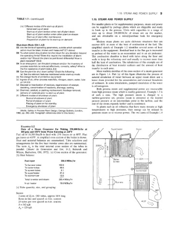
EXAMPLE 1.2
Data of a Steam Generator for Makiig 250,00OIb/hr at
450 psia and 650°F from Water Entering at 220°F
FueI oil of 18,500 Btu/lb is fired with 13% excess air at 80°F. Flue
gas leaves at 410°F. A simplified cross section of the boiler is shown.
Heat and material balances are summarized. Tube selections and
arrangements for the five heat transfer zones also are summarized.
The term A, is the total internal cross section of the tubes in
parallel. (Steam: Its Generation and Use, 14.2, Babcock and
arberton, OH, 1972). (a) Cross section of the generator:
(b) Heat balance:
I ‘Boiler +-loft+
Fuel input 335.5 MBtu/hr
To furnace tubes 162.0
To boiler tubes 68.5
To screen tubes, 8.1
To superheater 31.3
15.5
To economizer -
Total to water and steam 285.4 Mbtu/hr i
In air heater 18.0 MBtu/hr
(c) Tube quantity, size, and grouping:
Screen
2 rows of 2i-in. OD tubes, approx 18 ft long
Rows in line and spaced on 6-in. centers
23 tubes per row spaced on 6-in. centers
S = 542 sqft
A, = 129 sqft