Page 33 - Chemical Process Equipment - Selection and Design
P. 33

10  INTRODUCTION
               EXAMPLE l.%(continued)
               Superheater                                          Rows in line and spaced on 3-in. centers
                12 rows of 21411.  OD tubes (0.165-in. thick),      47 tubes per row spaced on 3-in. centers
                  17.44 ft long                                     S = 2460 sqft
                Rows in line and spaced on 3t-in. centers          A,  = 42 sqft
                23 tubes per row spaced on 6-in. centers          Air heater
                S = 3150 sqft                                       53 rows of 2-in.  OD tubes (0.083-in. thick),
                A,  = 133 sqft                                       approx 13 ft long
               Boiler                                               Rows in line and spaced on 2i-in. centers
                25 rows of  244x1.  OD tubes, approx 18 ft long     41 tubes per row spaced on 3i-in. centers
                Rows in line and spaced on 3a-in. centers           S = 14,800 sqft
                35 tubes per row spaced on 4-in. centers            A,  (total internal cross section area of 2173 tubes)
                S = 10,300 sqft                                       = 39.3 sqft
                A,  = 85.0 sqft                                     A,  (clear area between tubes for crossflow of  air)
               Economizer                                             = 70 sqft
                 10 rows of 2-in. OD tubes (0.148-in. thick),       Air temperature entering air heater = 80°F
                  approx 10 ft long


                                    Steam out
                      (a)                                                Gas   Steam Coil
                                                                   (''   Outlet   Air Heater


                                                                                                          Coa  I
                                                                                                      fl


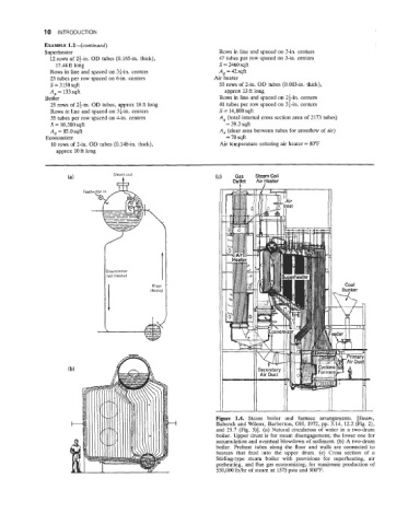
                                                                   Figure  1.4.  Steam  boiler  and  furnace  arrangements.  [Steam,
                                                                   Babcock and Wilcox, Barberton, OH, 1972, pp. 3.14, 12.2 (Fig. 2),
                                                                   and 25.7  (Fig.  5)].  (a) Natural  circulation of  water in a two-drum
                                                                   boiler. Upper drum is for steam disengagement; the lower one for
                                                                   accumulation and eventual blowdown of  sediment. (b) A two-drum
                                                                   boiler.  Preheat  tubes  along the  floor  and  walls  are  connected to
                                                                   heaters  that  feed  into  the  upper  drum.  (c)  Cross  section  of  a
                                                                   Stirling-type  steam  boiler  with  provisions  for  superheating,  air
                                                                   preheating,  and flue gas economizing; for maximum production of
                                                                   550,000 lb/hr of steam at 1575 psia and 900°F.
   28   29   30   31   32   33   34   35   36   37   38