
Page 69 - Chemical Process Equipment - Selection and Design
P. 69
3.1. FEEDBACK CONTROL 41
3. Derivative, in which the corrective action is proportional to the of cooling water is fixed accordingly. Suppose the heat load is
rate at which the error is being generated. doubled suddenly because of an increase in the reactor contents. At
steady state the valve will remain 50% open so that the water flow
The relation between the change in output rn - rn, and input e rate also will remain as before. Because of the greater rate of heat
signals accordingly is represented by evolution, however, the temperature will rise to a higher but still
steady value. On the other hand, the corrective action of an integral
rn - rn, = K, (e + :; le dt -k controller depends on displacement of the temperature from the
dt
original set point, so that this mode of control will restore the
original temperature.
Just how these modes of action are achieved in relatively The constants Kp, K,, and Kd are settings of the instrument.
inexpensive pneumatic or electrical devices is explained in books on When the controller is hooked up to the process, the settings
control instruments, for example, that of Considine (Process appropriate to a desired quality of control depend on the inertia
Instruments and Controls Handbook, Sec. 17, 1974). The low prices (capacitance) and various response times of the system, and they
and considerable flexibility of PID controllers make them the can be determined by field tests. The method of Ziegler and Nichols
dominant types in use, and have discouraged the development of used in Example 3.1 is based on step response of a damped system
possibly superior types, particularly as one-shot deals which would and provides at least approximate values of instrument settings
be the usual case in process plants. Any desired mode of action can which can be further fine-tuned in the field.
be simulated by a computer, but at a price. The kinds of controllers suitable for the common variables may
A capsule summary of the merits of the three kinds of be stated briefly:
corrective action can be made. The proportional action is rapid but
has a permanent offset that increases a5 the action speeds up. The Variable Controller
addition of integral action reduces or entirely eliminates the offset
but has a more sluggish response. The further addition of derivative Flow and liquid pressure PI
action speeds up the eorrection. The action of a three-mode PID Gas pressure P
Liquid level
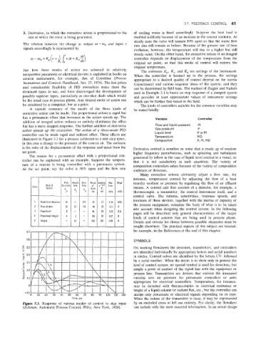
controller can be made rapid and without offset. These effects are Temperature P or PI
PID
illustrated in Figure 3.3 for a process subjected to a unit step upset, Composition P, PI, PID
in this case a change in the pressure of the control air. The ordinate
is the ratio of the displacements of the response and upset from the Derivative control is sensitive to noise that is made up of random
set point. higher frequency perturbations, such as spiashing and turbulence
The reason for a permanent offset with a proportional con- generated by inflow in the case of liquid level control in a vessel, so
troller can be explained with an example. Suppose the tempera- that it is not satisfactory in such situations. The variety of
ture of a reactor is being controlled with a pneumatic system. composition controllers arises because of the variety of composition
At the set point, say the valve is 50% open and the flow rate analyzers or detectors.
Many corrective actions ultimately adjust a flow rate, for
instance, temperature control by adjusting the flow of a heat
transfer medium or pressure by regulating the flow of an effluent
stream. A control unit thus consists of a detector, for example, a
thermocouple, a transmitter, the control instrument itself, and a
control valve. The natures, sensitivities, response speeds, and
locations of these devices, together with the inertia capacity of
the process equipment, comprise the body of what is to be taken
into account when designing the control system. In the following
pages will be described only general characteristics of the major
kinds of control systems that are being used in process plants.
Details and criteria for choice between possible alternates must be
sought elsewhere. The practical aspects of this subject are treated,
for example, in the References at the end of this chapter.
SYMBOLS
On working flowsheets the detectors, transmitters, and controllers
are identified individually by appropriate letters and serial numbers
in circles. Control valves are identified by the letters CV- followed
by a serial number. When the intent is to show only in general the
kind of control system, no special symbol is used for detectors, but
simply a point of contact of the signal line with the equipment or
process line. Transmitters are devices that convert the measured
variable into air pressure for pneumatic controllers or units
appropriate for electrical controllers. Temperature, for instance,
may be detected with thermocouples or electrical resistance or
height of a liquid column or radiant flux, etc., but the controller can
accept only pneumatic or electrical signals depending on its type.
Time, sec When the nature of the transmitter is clear, it may be represented
Figure 3.3. Response of various modes of control to step input by an encircled cross or left out entirely. For clarity, the flowsheet
(Eckimun, Automatic Psocess Control, Wiley, New York, 1958). can include only the most essential information. In an actual design