
Page 132 - Chemical engineering design
P. 132
112
CHEMICAL ENGINEERING
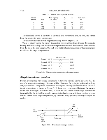
Data for heat integration problem
Stream Table 3.3. Heat capacity T s T t Heat load
number Type CP, kW/ ° C ° C ° C kW
1 hot 3.0 180 60 360
2 hot 1.0 150 30 120
3 cold 2.0 20 135 230
4 cold 4.5 80 140 270
The heat load shown in the table is the total heat required to heat, or cool, the stream
from the source to target temperature.
The four streams are shown diagrammatically below, Figure 3.18:
There is clearly scope for energy integration between these four streams. Two require
heating and two cooling; and the stream temperatures are such that heat can be transferred
from the hot to the cold streams. The task is to find the best arrangement of heat exchangers
to achieve the target temperatures.
CP = 3.0 kW/°C
Stream 1 180°C 60°C
1.0
Stream 2 150°C 30°C
2.0
Stream 3 20°C 135°C
4.5
Stream 4 80°C 140°C
Figure 3.18. Diagrammatic representation of process streams
Simple two-stream problem
Before investigating the energy integration of the four streams shown in Table 3.3, the
use of a temperature-enthalpy diagram will be illustrated for a simple problem involving
only two streams. The general problem of heating and cooling two streams from source to
target temperatures is shown in Figure 3.19. Some heat is exchanged between the streams
in the heat exchanger. Additional heat, to raise the cold stream to the target temperature,
is provided by the hot utility (usually steam) in the heater; and additional cooling to bring
the hot stream to its target temperature, by the cold utility (usually cooling water) in the
cooler.
Cold
utility
T T t
Hot s
stream
Cold
stream
T t T s
Hot Exchanger
utility
Figure 3.19. Two-stream exchanger problem