Page 139 - Chemical engineering design
P. 139

FUNDAMENTALS OF ENERGY BALANCES
                     Matching streams 1 and 4 and transferring the full amount of heat required to bring
                   stream 1 to the pinch temperature gives:                               119
                                              H ex D CP T s   T pinch
                                          H ex D 3.0 180   90  D 270 kW
                     This will also satisfy the heat load required to bring stream 4 to its target temperature:
                                          H ex D 4.5 140   80  D 270 kW
                     2. Stream 2 can be matched with stream 3, whilst satisfying the heat capacity restriction.
                   Transferring the full amount to bring stream 3 to the pinch temperature:
                                          H ex D 1.0 150   90  D 60 kW

                     3. The heat required to bring stream 3 to its target temperature, from the pinch temper-
                   ature, is:
                                           H D 2.0 135   80  D 110 kW
                     So a heater will have to be included to provide the remaining heat load:
                                            H hot D 110   60 D 50 kW

                     This checks with the value given by the problem table, Figure 3.23b.
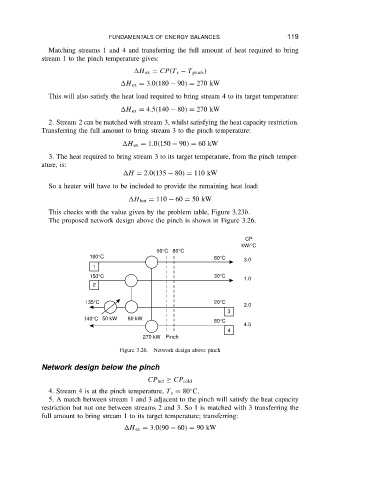
                     The proposed network design above the pinch is shown in Figure 3.26.

                                                                              CP
                                                                             kW/°C
                                                    90°C  80°C
                                 180°C                               60°C     3.0
                                  1
                                 150°C                               30°C
                                                                              1.0
                                  2

                                135°C                                20°C
                                                                              2.0
                                                                         3
                               140°C 50 kW  60 kW                    80°C
                                                                              4.5
                                                                         4
                                                270 kW Pinch
                                          Figure 3.26.  Network design above pinch


                   Network design below the pinch
                                                  CP hot ½ CP cold
                                                              Ž
                     4. Stream 4 is at the pinch temperature, T s D 80 C.
                     5. A match between stream 1 and 3 adjacent to the pinch will satisfy the heat capacity
                   restriction but not one between streams 2 and 3. So 1 is matched with 3 transferring the
                   full amount to bring stream 1 to its target temperature; transferring:
                                           H ex D 3.0 90   60  D 90 kW
   134   135   136   137   138   139   140   141   142   143   144