
Page 421 - Chemical process engineering design and economics
P. 421
Reactor Design 401
Table 7.13 Steps in a Catalytic Reaction (Source: adapted from Ref.
.16);_________________________________________
1. Mass transfer of reactants from the fluid to the pore entrances of the catalyst
pellet
2. Diffusion of reactants through the porous catalyst to the internal catalytic sur-
face
3. Adsorption of reactants on the catalyst surface
4. Reaction on the catalyst surface
5. Desorption of products from the surface
6. Diffusion of products from the interior of the pellet to the pore entrance
7. Mass transfer of products from the pore entrance to the fluid
Major
Flow Lines
Jet Action in
Center Causes
Cavity in a
Catalyst Bed
Top of Catalyst
Bed or Tube
Sheet of Multi-
tubular Reactor
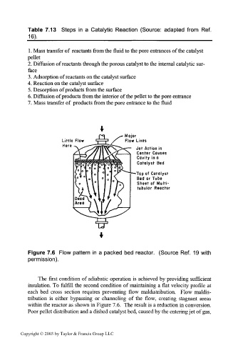
Figure 7.6 Flow pattern in a packed bed reactor. (Source Ref. 19 with
permission).
The first condition of adiabatic operation is achieved by providing sufficient
insulation. To fulfill the second condition of maintaining a flat velocity profile at
each bed cross section requires preventing flow maldistribution. Flow maldis-
tribution is either bypassing or channeling of the flow, creating stagnant areas
within the reactor as shown in Figure 7.6. The result is a reduction in conversion.
Poor pellet distribution and a dished catalyst bed, caused by the entering jet of gas,
Copyright © 2003 by Taylor & Francis Group LLC