
Page 422 - Chemical process engineering design and economics
P. 422
402 Chapter 7
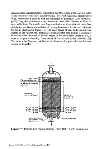
can cause flow maldistribution. Distributing the flow evenly at the inlet and outlet
of the reactor prevents flow maldistribution. To avoid bypassing, Trambouze et
al. [8] recommend a pressure drop per unit length of packing of 2500 Pa/m (0.11
psi/ft). They also recommend a bed diameter to mean pellet diameter of 10 to re-
duce wall effects. To provide even flow distribution requires inlet and outlet flow
distributors and layers of inert balls of varying diameters at the top and bottom of
the bed as illustrated in Figure 7.7. The upper layers of large balls also prevents
dishing of the catalyst bed. Tarhan [25] estimated that back mixing is essentially
eliminated when the ratio of the bed length to the mean pellet diameter, L/d, is
equal to or greater than fifty. Most industrial reactors satisfy this condition [25].
The mean pellet diameter is defined as the diameter of a sphere that has the same
volume as the pellet.
6'loyir l" belli-
6" optional additional layers,
of progressively smaller balls
for iiepwed distribution and
icalf removal
cotalyit Beil
H/8" « l/8'pellsts) Catalyst Bed
M/4"< 1/4" \
\ pellets I
3" layer l/4"bolls " ~ ~ 13 loyer 3/B bolls
4"loyer 1/z" tolls _ 4 loyer 1/2 tolls
5" loyer 5/4" balls } 5" layer 3/4" balls
3/4" balls 3/4" bolls
Reactor Outlet Screen Catalyst Dump Flange
with Continuous Slotted
Openings
Figure 7.7 Packed bed reactor design. From Ref. 19 with permission.
Copyright © 2003 by Taylor & Francis Group LLC