Page 67 - Circuit Analysis II with MATLAB Applications
P. 67

Chapter 2


                                                                                       Resonance


         T     his chapter defines series and parallel resonance. The quality factor   is then defined in terms
                                                                             Q
               of the series and parallel resonant frequencies. The half-power frequencies and bandwidth are
               also defined in terms of the resonant frequency.


         2.1 Series Resonance

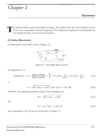
         Consider phasor series RLC  circuit of Figure 2.1.


                                                               `
                                         V S       R       jZL

                                                 I
                                                             1jZC
                                                               e

                                       Figure 2.1. Series RLC phasor circuit

                        Z
         The impedance   is
                                                                     1
                                   Phasor Voltage
                                                                                §
                                                                                      1 ·
                Impedance =   Z =  --------------------------------------- =  V S  R +  jZL +  ---------- =  R +  j ZL –  --------       (2.1)
                                                     ------ =
                                   Phasor Current    I              jZC         ©     ZC  ¹
         or
                                      2              2     – 1
                              Z =   R +     ZL –  1 ZC ‘ tan     ZL1 ZC e  R                     (2.2)
                                                                 –


                                                e
                                                                    e
         Therefore, the magnitude and phase angle of the impedance are:
                                                 2
                                         Z =    R +     ZL –  1 ZC    2                          (2.3)
                                                            e
         and
                                         T =   tan – 1    ZL –  1 ZC e  R                        (2.4)

                                                           e
                                          Z
         The components of  Z   are shown on the plot of Figure 2.2.


        Circuit Analysis II with MATLAB Applications                                             2-1
        Orchard Publications
   62   63   64   65   66   67   68   69   70   71   72