Page 71 - Circuit Analysis II with MATLAB Applications
P. 71

Quality Factor Q  in Series Resonance
                                                                           0s

         Then, by definition


                                                  Z L      1
                                                   0
                                           Q 0S  =  --------- =  --------------                  (2.9)
                                                   R
                                                         Z RC
                                                          0
                                   Quality Factor at Series Resonance
         In a practical circuit, the resistance   in the definition of Q 0S  above, represents the resistance of the
                                          R
         inductor and thus the quality factor Q 0S  is a measure of the energy storage property of the inductance
         L   in relation to the energy dissipation property of the resistance   of that inductance.R


         In terms of Q 0S , the magnitude of the voltages across the inductor and capacitor are


                                         V L0  =  V C0  =  Q 0S  V S                           (2.10)

         and therefore, we say that there is a “resonant” rise in the voltage across the reactive devices and it is
         equal to the Q 0S  times the applied voltage. Thus in Example 2.1,


                                              V       V      1000    25
                                               L0
                                                       C0
                                      Q 0S  =  ------------ =  ------------ =  ------------ =  ------
                                                              120
                                                                      3
                                                      V
                                              V
                                                        S
                                                S
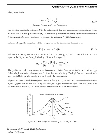
         The quality factor   is also a measure of frequency selectivity. Thus, we say that a circuit with a high
                          Q
                                             Q
         Q  has a high selectivity, whereas a low   circuit has low selectivity. The high frequency selectivity is
         more desirable in parallel circuits as we will see in the next section.
         Figure 2.5 shows the relative response versus   for Q =  25 50 , and  100  where we observe that

                                                    Z
         highest   provides the best frequency selectivity, i.e., higher rejection of signal components outside
                Q
         the bandwidth BW =   Z –  Z 1  which is the difference in the 3dB  frequencies.
                               2
                                          Selectivity Curves for Different Qs
                               1.2                                  Q=25
                              Relative Response (gain)  0.8         Q=50
                               1.0
                               0.6
                                                                      Q=100
                               0.4
                               0.2
                               0.0                  Z 1 Z 0 Z 2
                                                     Z  r/s
                              Figure 2.5. Selectivity curves with Q =  25 50 , and 100


        Circuit Analysis II with MATLAB Applications                                              2-5
        Orchard Publications
   66   67   68   69   70   71   72   73   74   75   76