Page 76 - Circuit Analysis II with MATLAB Applications
P. 76

Chapter 2  Resonance


                                          1         1  V        1
                                                         S
                                  I    =  ---------V =  ------------------ =  -------------- I  (2.19)
                                   L0    Z L   0   Z L G      Z GL   S
                                                               0
                                           0
                                                    0
         At parallel resonance the left sides of (2.18) and (2.19) are equal and therefore,
                                                Z C       1
                                                  0
                                                ---------- =  --------------
                                                  G     Z GL
                                                         0
         Now, by definition
                                                 Z C       1
                                                   0
                                          Q 0P  =  ---------- =  --------------                (2.20)
                                                        Z GL
                                                  G
                                                          0
                                 Quality Factor at Parallel Resonance
         The above expressions indicate that at parallel resonance, it is possible to develop high currents
         through the capacitors and inductors. This was found to be true in Example 2.2.


         2.5  General Definition of Q

         The general (and best) definition of   is
                                          Q


                                           Maximum Energy Stored
                                 Q =   2S------------------------------------------------------------------------------  (2.21)
                                         Energy Dissipated per Cycle

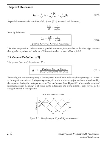
         Essentially, the resonant frequency is the frequency at which the inductor gives up energy just as fast
         as the capacitor requires it during one quarter cycle, and absorbs energy just as fast as it is released by
         the capacitor during the next quarter cycle. This can be seen from Figure 2.11 where at the instant of
         maximum current the energy is all stored in the inductance, and at the instant of zero current all the
         energy is stored in the capacitor.


                                            W L  & W C  in Series RLC Circuit

                                              W L     W C
                                      Energy (J)                        Z


                                                      v C      i L

                               Figure 2.11. Waveforms for W L  and W C  at resonance


        2-10                                                Circuit Analysis II with MATLAB Applications

                                                                                  Orchard Publications
   71   72   73   74   75   76   77   78   79   80   81