
Page 73 - Circuit Analysis II with MATLAB Applications
P. 73
Parallel Resonance
+
I S C I
V G I G L ` I L C
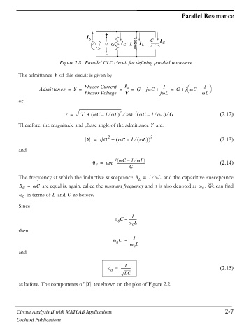
Figure 2.8. Parallel GLC circuit for defining parallel resonance
The admittance of this circuit is given by
Y
1
1 ·
§
S
Admittan ce = Y = Phasor Current I ---- = G + jZC + --------- = G + j ZC – -------
------------------------------------- =
Phasor Voltage V jZL © ZL ¹
or
2 2 – 1
Y = G + ZC1 ZL tan ZC – 1 ZL e G (2.12)
–
e
e
Therefore, the magnitude and phase angle of the admittance are:
Y
2
Y = G + ZC 1 e ZL 2 (2.13)
–
and
– 1 ZC – 1 ZL
e
T = tan --------------------------------- (2.14)
Y
G
The frequency at which the inductive susceptance B = 1 ZL and the capacitive susceptance
e
L
B C = ZC are equal is, again, called the resonant frequency and it is also denoted as Z 0 We can find
C
L
Z in terms of and as before.
0
Since
1
Z C – ---------
0
Z L
then, 0
1
Z C = ---------
0
Z L
and 0
1
Z = ----------- (2.15)
0
LC
as before. The components of Y are shown on the plot of Figure 2.2.
Circuit Analysis II with MATLAB Applications 2-7
Orchard Publications