Page 68 - Circuit Analysis II with MATLAB Applications
P. 68

Chapter 2  Resonance


                                               Series Resonance Curves
                                            |Z|                  ZL

                                   Magnitude of Impedance  0  R  Z 0   1 / ZC  Z


                                                         ZL 1 / ZC
                                                    Radian Frequency

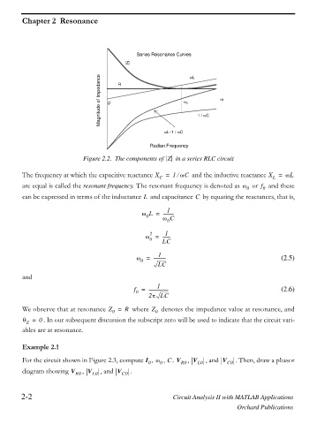
                             Figure 2.2. The components of  Z   in a series RLC circuit

         The frequency at which the capacitive reactance X C  =  1 ZC  and the inductive reactance X =  ZL
                                                             e
                                                                                              L
                                                                                          f
         are equal is called the resonant frequency. The resonant frequency is denoted as Z 0  or   and these
                                                                                          0
         can be expressed in terms of the inductance   and capacitance   by equating the reactances, that is,
                                                                   C
                                                  L
                                                          1
                                                 Z L =  ----------
                                                   0
                                                        Z C
                                                          0
                                                         1
                                                    2
                                                  Z =   -------
                                                    0
                                                        LC
                                                       1
                                               Z =   -----------                                 (2.5)
                                                 0
                                                       LC
         and
                                                      1
                                               f =  ------------------                           (2.6)
                                               0
                                                    2S LC
         We observe that at resonance Z =  R   where Z 0   denotes the impedance value at resonance, and
                                       0
         T =  0 . In our subsequent discussion the subscript zero will be used to indicate that the circuit vari-
          Z
         ables are at resonance.


         Example 2.1

         For the circuit shown in Figure 2.3, compute I 0  , Z 0 , , V R0 , V L0  , and V C0  . Then, draw a phasor
                                                          C
         diagram showing V R0 ,  V L0  , and V C0  .


        2-2                                                 Circuit Analysis II with MATLAB Applications

                                                                                  Orchard Publications
   63   64   65   66   67   68   69   70   71   72   73