
Page 70 - Circuit Analysis II with MATLAB Applications
P. 70
Chapter 2 Resonance
|V | = 1000 V
L0
V = 120 V
R0
|V | = 1000 V
C0
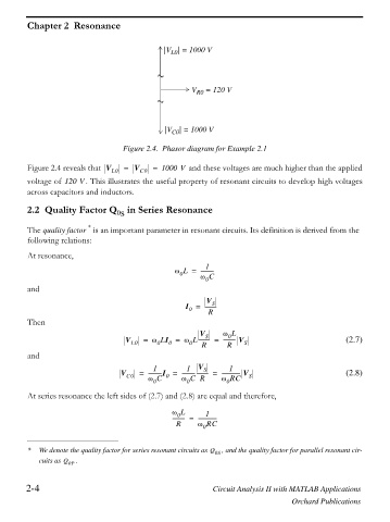
Figure 2.4. Phasor diagram for Example 2.1
Figure 2.4 reveals that V L0 = V C0 = 1000 V and these voltages are much higher than the applied
voltage of 120 V . This illustrates the useful property of resonant circuits to develop high voltages
across capacitors and inductors.
2.2 Quality Factor Q in Series Resonance
0s
*
The quality factor is an important parameter in resonant circuits. Its definition is derived from the
following relations:
At resonance,
1
Z L = ----------
0
Z C
and 0
V
S
I = ---------
0
R
Then
V Z L
0
S
V L0 = Z LI = Z L--------- = --------- V S (2.7)
0
0
0
R
R
and
1 1 V S 1
V C0 = ----------I = ------------------- = -------------- V S (2.8)
0
Z C
Z C R
Z RC
0
0
0
At series resonance the left sides of (2.7) and (2.8) are equal and therefore,
Z L 1
0
--------- = --------------
R Z RC
0
* We denote the quality factor for series resonant circuits as Q 0S , and the quality factor for parallel resonant cir-
cuits as Q 0P .
2-4 Circuit Analysis II with MATLAB Applications
Orchard Publications