Page 74 - Circuit Analysis II with MATLAB Applications
P. 74

Chapter 2  Resonance


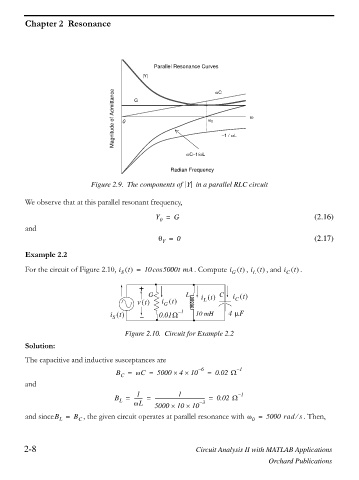
                                               Parallel Resonance Curves
                                            |Y|                   ZC

                                   Magnitude of Admittance  0  G  Z 0   1 / ZL  Z


                                                         ZC 1/ZL

                                                    Radian Frequency

                            Figure 2.9. The components of  Y   in a parallel RLC circuit

         We observe that at this parallel resonant frequency,

                                                Y =  G                                         (2.16)
                                                 0
         and
                                                 T =  0                                        (2.17)
                                                  Y
         Example 2.2

                                                                           ,
                                                                                         t
                                                                               t
                                                                         t
         For the circuit of Figure 2.10, i t   =  10cos 5000t mA  . Compute i    i     , and i    .
                                                                             L
                                                                       G
                                                                                       C
                                     S
                                           +
                                              G          L   i     C   i
                                                                          t
                                                                t
                                                     t
                                          vt      i         `  L        C
                                                  G
                                                      – 1             4 PF
                                  i t            0.01:      10 mH
                                   S
                                       Figure 2.10. Circuit for Example 2.2
         Solution:
         The capacitive and inductive susceptances are
                                    B  =  ZC =  5000 u  4 u  10 – 6  =  0.02 : – 1
                                     C
         and
                                          1
                                                      1
                                   B =   ------- =  ----------------------------------------- =  0.02 : – 1
                                     L
                                         ZL    5000 u  10 u 10 – 3
         and sinceB =  B C , the given circuit operates at parallel resonance with Z =  5000 rad s . Then,
                                                                                          e
                   L
                                                                             0
        2-8                                                 Circuit Analysis II with MATLAB Applications
                                                                                  Orchard Publications
   69   70   71   72   73   74   75   76   77   78   79