
Page 96 - Circuit Analysis II with MATLAB Applications
P. 96
Chapter 2 Resonance
Z IN f = 10 KHz = z + 111.12 + j127.72 + 1 = z + 113.12 + j127.72 : (2)
1
1
The expression of (2) will be minimum if we let z = – j127.72 : at f = 10 KHz . Then, the
1
capacitor C 1 value must be such that 1 ZC = 127.72 or
e
1
C = -------------------------------------------- = 1.25 u 10 – 7 F = 0.125 PF
1
4
2S u 10 u 127.72
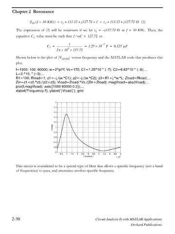
Shown below is the plot of V LOAD versus frequency and the MATLAB code that produces this
plot.
f=1000: 100: 60000; w=2*pi*f; Vs=170; C1=1.25*10^( 7); C2=6.62*10^( 9);...
L=2.*10.^( 3);...
R1=100; Rload=1; z1= j./(w.*C1); z2= j./(w.*C2); z3=R1+j.*w.*L; Zload=Rload;...
Zin=z1+z2.*z3./(z2+z3); Vload=Zload.*Vs./(Zin+Zload); magVload=abs(Vload);...
plot(f,magVload); axis([1000 60000 0 2]);...
xlabel('Frequency f'); ylabel('|Vload|'); grid
This circuit is considered to be a special type of filter that allows a specific frequency (not a band
of frequencies) to pass, and attenuates another specific frequency.
2-30 Circuit Analysis II with MATLAB Applications
Orchard Publications