Page 99 - Circuit Analysis II with MATLAB Applications
P. 99

The Unit Step Function


                                                    ­ 0     t    t 0
                                         u t –  t    0  =  ®                                     (3.5)

                                          0
                                                    ¯ 1     t !  t 0
                                                            1
        If the unit step function changes abruptly from   to   at t =  t –  0  , it is denoted as u t +   0  t    0  . Its
                                                       0
        waveform and definition are as shown in Figure 3.5 and relation (3.6).

                                               1  u t +   0  t    0


                                            t 0  0                  t

                                       Figure 3.5. Waveform for u t +  t    0

                                                                0
                                                    ­ 0     t    t –  0
                                        u t +   0  t    0  =  ®                                  (3.6)
                                                    ¯ 1     t !  t –  0


        Example 3.1

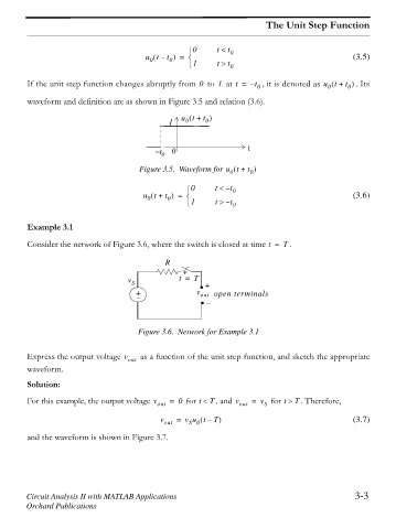
        Consider the network of Figure 3.6, where the switch is closed at time t =  . T

                                              R

                                    v S           t =  T  +
                                      +               v out open terminals


                                       Figure 3.6. Network for Example 3.1


        Express the output voltage v out  as a function of the unit step function, and sketch the appropriate
        waveform.

        Solution:
        For this example, the output voltage v out  =  0   for t    T , and v out  =  v S   for t !  T . Therefore,


                                                         =
                                             v out  v u t –  T                                   (3.7)
                                                    S 0
        and the waveform is shown in Figure 3.7.


        Circuit Analysis II with MATLAB Applications                                              3-3
        Orchard Publications
   94   95   96   97   98   99   100   101   102   103   104