
Page 138 - Complete Wireless Design
P. 138
Amplifier Design
Amplifier Design 137
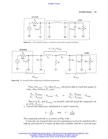
Figure 3.37 A pi network used in a resistive and reactive source and load.
Figure 3.38 Pi network before combining calculated components.
Thus, if X X , then X will not be able to reach the proper X
CSTRAY C1 CTOTAL C
value. Also, increase X until:
C1
X X X X
CSTRAY1
C1
CSTRAY1
C1
X X or X
X X CTOTAL C1 X X CNEW
C1 CSTRAY1 C1 CSTRAY1
This is so X and X , in parallel, will still equal the computed val-
C1 CSTRAY1
ue of X (X ).
C1 CTOTAL
7. Convert the reactances calculated to L and C values by:
X 1
L and C
2 f 2 fX
The completed network is as shown as Fig. 3.39.
T networks are required when two low impedances need to be matched with a
high Q, and must be of a higher Q than that available with the L network type.
Downloaded from Digital Engineering Library @ McGraw-Hill (www.digitalengineeringlibrary.com)
Copyright © 2004 The McGraw-Hill Companies. All rights reserved.
Any use is subject to the Terms of Use as given at the website.