Page 141 - Complete Wireless Design
P. 141

Amplifier Design


            140  Chapter Three


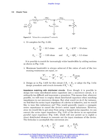
                        Figure 3.41 Values for a completed T network.

                        4. Or complete for Fig. 3.43b:

                                        R
                                         P
                                  X          22.7 ohms     and    X     Q"R"   19 ohms
                                   P2   Q                           S2
                                       "R"
                                 X           3.95 ohms     and     X    QR   3.3 ohms
                                  P1    Q                           S1     S

                          It is possible to match for increasingly wider bandwidths by adding sections
                        as shown in Fig. 3.44:

                        1. Maximum bandwidth is always achieved if the ratios of each of the two
                           ensuing resistances are equal, or:
                                           "R"      "R"     "R"          R
                                              1
                                                                           LARGER
                                                       2       3     . . .
                                         R          "R"     "R"           "R"
                                          SMALLER      1       2             n
                        2. Design as in Fig. 3.43b for this circuit if R   R , or adopt the Fig. 3.43a
                                                                   L     S
                           design procedure and circuit elements if R   R .
                                                                  L    S
                        Impedance matching with distributed circuits. Even though it is possible to
                        design low-value distributed series capacitors into a microwave circuit, it is
                        ordinarily too difficult and inaccurate a procedure. This means that, wherever
                        possible, we will want to employ shunt distributed capacitors when matching
                        impedances in our microwave designs. But what would we do if, for instance,
                        we find that the series input impedance of a device is inductive, and we would
                        like to tune this inductance out? This would generally require a conjugate
                        series capacitance to cancel the device’s series input inductance. However,
                        since we would like to get away from using a lumped series capacitor, we can
                        convert the series input impedance (Fig. 3.45) of the device to an equivalent
                        parallel input impedance (Fig. 3.46), which will now permit us to exploit a
                        shunt distributed element to resonate out the input reactance of the device.
                        The formulas to accomplish this conversion are:
                                                     X  2                R R
                                                      S
                                                                           P
                                                                             S
                                          R   R             and     X
                                            P    S   R               P    X
                                                       S                    S
                   Downloaded from Digital Engineering Library @ McGraw-Hill (www.digitalengineeringlibrary.com)
                               Copyright © 2004 The McGraw-Hill Companies. All rights reserved.
                                Any use is subject to the Terms of Use as given at the website.
   136   137   138   139   140   141   142   143   144   145   146