
Page 145 - Complete Wireless Design
P. 145
Amplifier Design
144 Chapter Three
2. Convert series R ± jX to parallel as required. Whether to employ parallel or
series will depend on whether it would be easier, with microstrip, to resonate
out the reactance in series or in a parallel equivalence. If a distributed part
must be used for this purpose, a shunt capacitor is always desired.
3. Calculate the required microstrip width and length, at the frequency of
interest, to simulate a lumped value that will cancel out the reactive com-
ponent of the device being matched, making the input or output R j0.
Lumped microwave capacitors and inductors can also be utilized if the
microstrip part is unrealizable because it would be inordinately over 30
degrees in length.
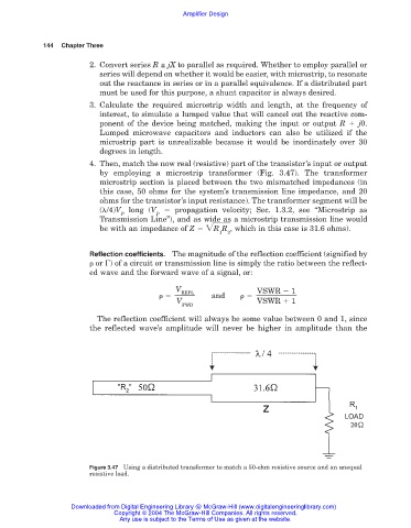
4. Then, match the now real (resistive) part of the transistor’s input or output
by employing a microstrip transformer (Fig. 3.47). The transformer
microstrip section is placed between the two mismatched impedances (in
this case, 50 ohms for the system’s transmission line impedance, and 20
ohms for the transistor’s input resistance). The transformer segment will be
( /4)V long (V propagation velocity; Sec. 1.3.2, see “Microstrip as
P P
Transmission Line”), and as wide as a microstrip transmission line would
be with an impedance of Z R R , which in this case is 31.6 ohms).
1 2
Reflection coefficients. The magnitude of the reflection coefficient (signified by
or ) of a circuit or transmission line is simply the ratio between the reflect-
ed wave and the forward wave of a signal, or:
V VSWR 1
REFL
and
V VSWR 1
FWD
The reflection coefficient will always be some value between 0 and 1, since
the reflected wave’s amplitude will never be higher in amplitude than the
Figure 3.47 Using a distributed transformer to match a 50-ohm resistive source and an unequal
resistive load.
Downloaded from Digital Engineering Library @ McGraw-Hill (www.digitalengineeringlibrary.com)
Copyright © 2004 The McGraw-Hill Companies. All rights reserved.
Any use is subject to the Terms of Use as given at the website.