
Page 144 - Complete Wireless Design
P. 144
Amplifier Design
Amplifier Design 143
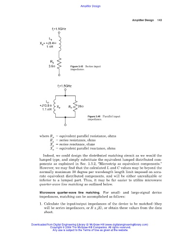
Figure 3.45 Series input
impedance.
Figure 3.46 Parallel input
impedance.
where R equivalent parallel resistance, ohms
P
R series resistance, ohms
S
X series reactance, ohms
S
X equivalent parallel reactance, ohms
P
Indeed, we could design the distributed matching circuit as we would the
lumped type, and simply substitute the equivalent lumped distributed com-
ponents as explained in Sec. 1.3.2, “Microstrip as equivalent components.”
However, we may find that the calculated L and C values may be beyond the
normally maximum 30 degree per wavelength length limit imposed on accu-
rate equivalent distributed components, and will be either unrealizable or
inferior to a lumped part. Thus, it may be far easier to utilize microwave
quarter-wave line matching as outlined below.
Microwave quarter-wave line matching. For small- and large-signal device
impedances, matching can be accomplished as follows:
1. Calculate the input/output impedances of the device to be matched (they
will be series impedances, or R ± jX), or obtain these values from the data
sheet.
Downloaded from Digital Engineering Library @ McGraw-Hill (www.digitalengineeringlibrary.com)
Copyright © 2004 The McGraw-Hill Companies. All rights reserved.
Any use is subject to the Terms of Use as given at the website.