
Page 133 - Complete Wireless Design
P. 133
Amplifier Design
132 Chapter Three
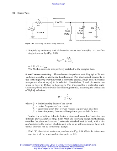
Figure 3.30 Canceling the load’s stray reactance.
3. Simplify by combining both of the inductors we now have (Fig. 3.31) with a
single inductor by (Fig. 3.32):
L L
2
1
L
NEW L L
1 2
or 2.22 nH L
NEW
The 50-ohm source is now perfectly matched to the complex load.
Pi and T network matching. Three-element impedance matching (pi or T) net-
works are popular in narrowband applications. The narrowband popularity is
due to the higher Q over that which L networks possess, yet pi and T networks
also permit almost any Q to be selected. Nonetheless, T and pi circuits can
never be lower in Q than an L network. The Q desired for a particular appli-
cation may be calculated with the following formula, assuming the utilization
of high-Q inductors:
f
c
Q
(f f )
2 1
where Q loaded quality factor of the circuit
f center frequency of the circuit
C
f upper frequency that we will require to pass with little loss
2
f lower frequency that we will require to pass with little loss
1
Employ the guidelines below to design a pi network capable of matching two
different pure resistances (Fig. 3.33). With the following design methodology,
consider the pi network as two L networks attached back to back, with a vir-
tual resistor in the center; which is used only as an aid in designing these net-
works, and will not be in the final design:
1. Find “R”, the virtual resistance, as shown in Fig. 3.34. (Note: In this exam-
ple, the Q of the pi network is chosen to be 10):
Downloaded from Digital Engineering Library @ McGraw-Hill (www.digitalengineeringlibrary.com)
Copyright © 2004 The McGraw-Hill Companies. All rights reserved.
Any use is subject to the Terms of Use as given at the website.